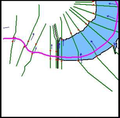
The modeler should review of the HEC-RAS model being used in CWMS for real-time forecasting. The geometry in the model was built to provide inundation maps for real-time operations and can be laid out in a variety of ways depending on the structures in the system. The approach to setting up HEC-RAS alternatives for FDR is dependent on the features in the basin and how they were modeled in the existing geometry. The CWMS HEC-RAS model geometries predominately contain different combinations of the following features:

  • Headwater reservoirs
  • Tandem reservoirs, with reaches broken or continuous
  • Small levees (with insignificant impacts to stage)
  • Large levees (with significant impacts to stage)

Watersheds with headwater reservoirs, and/or small levees are the most simplistic and often require minimal modifications for FDR use. Watersheds with tandem reservoirs can be approached differently, based on whether the reaches are continuous at the dams. Similarly, the approach for basins with levees differs based on how removing the levees impacts river stages. The following sections provide more detail on each of the variations and how they can be set-up in HEC-RAS to compute FDR with CWMS.

Geometries with Headwater Reservoirs and/or Small Levees Only

The simplest geometry set up for computing FDR with CWMS is a watershed that contains headwater reservoirs only, and/or small levees. If the watershed contains exclusively these types of features, no geometry modifications are required.

Headwater only reservoirs exist in watersheds where there are no other reservoirs in series. Figure 1 illustrates an example of a watershed containing only headwater reservoirs. This image shows two headwater reservoirs in the system where cross sections begin downstream of the reservoirs.

Example HEC-RAS Geometry - Headwater Reservoirs


A small levee has minimal storage behind the levee, and, if removed, would have limited hydraulic impact on the river stages. Since these small levees have negligible impacts on river stages, the without-levee inundations can likely be estimated using the HEC-FIA Holdouts compute method. If using the HEC-FIA Holdouts approach is determined to be acceptable for the system, the need to create and compute additional HEC-RAS alternatives for the without-levee hydraulics is eliminated.

Geometries with Tandem Reservoirs (Discontinuous Reaches)

If there are tandem reservoirs in the system, or any routing through the reservoirs with cross sections, the HEC-RAS geometry could have been broken into multiple reaches at the downstream dam or upper extent of the downstream reservoir (i.e., no cross sections within the reservoir). For tandem reservoirs, these types of geometries can be utilized to compute the unregulated scenario by modifying both the upstream and downstream boundary conditions where the reaches are broken. Among geometries with tandem reservoirs, handling discontinuous reaches requires less effort for FDR use than geometries with continuous reaches. Figure 2 shows an example of a watershed with tandem reservoirs where the reach was broken at the downstream dam.

However, the limitation to this method is that the hydraulics of the unregulated flows through the downstream reservoir sites are not computed. Instead, hydrologic routing results from HEC-ResSim or HEC-HMS serve as the outflow boundary condition. The errors associated with the discontinuity in hydraulics might be acceptable for steeper watersheds, but for watersheds with less topographic relief, where backwater could impact the results at the reservoir site, merging the upstream and downstream reaches of the downstream reservoirs is a more acceptable methodology.

Example HEC-RAS Geometry - Tandem Reservoirs with Broken Reaches

For discontinuous reaches, you should decide how to select the pool boundary condition (i.e., the upstream of the dam) when computing the unregulated scenario. There are many methodologies on how to handle this issue and all have merit. The most ideal method is to apply a pre-project rating curve as the boundary condition. If one is not readily available, a shifted tailwater elevation versus discharge rating curve could suffice. There are, however, issues that can occur when using a rating curve. The most simplistic approach is to use a stage boundary condition and set the reservoir to an elevation within the conservation pool (i.e., winter/seasonal drawdown).

The least desirable approach to the boundary condition in the unregulated scenario is to use the observed pool elevation from the regulated event. This might result in artificially high stages in the upper reaches of the reservoir where high unregulated flows transition to the reservoir backwater. Careful engineering analysis and consideration should be given to selecting the appropriate boundary condition for these types of watersheds.

Geometries with Tandem Reservoirs (Continuous Reaches)

For HEC-RAS geometries with continuous reaches through downstream tandem reservoir(s), removing the inline structure representing the dam is required for the unregulated alternative. Since the reach is continuous through the reservoir, no additional boundary conditions are required. This setup results in the most accurate unregulated flows for the reaches downstream of all tandem reservoir(s) as the computed flows are derived from unsteady hydraulic routing.


Figure 4 HEC-RAS Geometry Tandem Reservoirs Continuous Reach

Reservoirs in operation for several decades and/or having significant sedimentation will likely have an abrupt change in cross section invert elevations across the dam. The abrupt change in elevations from the headwater side to tailwater side of the dam could cause instabilities in the HEC-RAS model. One way to address the instability is to modify the cross sections throughout the reservoir to represent a pre-project condition. You could also decide to use a small inline structure so that HEC-RAS computes weir flow at the drop and does not become unstable during the simulation.

Though a completely continuous HEC-RAS geometry produces the most accurate unregulated flow routing downstream of the tandem reservoir(s), flood damages computed around the reservoirs may need further scrutiny. There can be negative flood damages reduced for the areas immediately around and just upstream of the downstream tandem reservoir(s). In the regulated condition, the reservoir might potentially cause damage on structures and agricultural land that may have encroached on the flood plain around the reservoir. When compared to the unregulated condition, these areas might not experience flooding as the dam is not storing water and raising stages. This might be perfectly acceptable, as some districts may want to report on the impacts to the encroachments in and around their reservoirs. Regardless, careful analysis and consideration should be given to how these types of scenarios will be handed in the economics reporting stage.

Geometries with Levees

The first consideration to make in a basin with levees is whether or not the levees have an impact on in-channel stages. If the answer is yes, the next item to consider is whether these impacts are negligible in the scope of the calculations being performed for FDR. The following paragraphs should help determine the most appropriate path forward for the basins with levees.

The advantage of utilizing the HEC-FIA Holdouts Approach for computing FDR is that levee FDR is computed within the HEC-FIA logic, requiring only a regulated and unregulated HEC-RAS inundation. For smaller levee systems having minimal impact to the associated in-channel stages, using HEC-FIA to compute without-levee depths is appropriate. HEC-FIA simplifies the computation by applying the in-channel WSEs, or a fraction of in-channel WSEs to structures in leveed areas to compute damage. However, in the case of larger levees, removing the levee may result in impact on the mainstem river stages. The simplified assumptions in HEC-FIA would not be appropriate for that situation. Instead, an additional without-levee HEC-RAS geometry and plans are required to compute the hydraulics of the without-levee scenario.

When considering an approach, a good place to start is evaluating how the existing levee is modeled. For example, if the area behind a levee is modeled with a two-dimensional (2D) flow area due to the complexity of hydraulics or the size of the protected area, it would likely be beneficial to compute the without-levee hydraulics in HEC-RAS as the assumptions in HEC-FIA may not characterize the without-levee inundation well. On the other hand, if a small levee exists where the protected area would presumably fill like a bathtub if the levee were removed, using HEC-FIA to calculate the without-levee damages is likely appropriate.

If using HEC-FIA to calculate the without-levee FDR, storage areas and/or shapefiles need to be established for the leveed areas. Most HEC-RAS models developed for CWMS already have either a one-dimensional (1D) storage area or a 2D flow area to represent leveed areas. This is the preferred setup for levees, and nothing more is required for FDR. However, some older HEC-RAS models define levees within the cross sections. Shapefiles should be developed to represent the leveed area for the HEC-FIA model to utilize when evaluating inundated areas for FDR if the HEC-RAS geometry is set up using levee points with the cross sections. Additionally, you should be cautious of overtopping scenarios where unrealistic inundations and model instabilities can occur when WSEs exceed the levee points.

Figure 4 provides an example of an older HEC-RAS model that uses levee points within cross sections and an example of the shapefile created to define the leveed area for use in HEC-FIA.

HEC-RAS Cross Sections with Levee Points


If HEC-RAS is used to compute hydraulics for the without-levee condition, multiple approaches can be taken to modify the geometries to run a without-levee alternative. For geometries with lateral structures and 1D storage areas or 2D flow areas, the simplest way to represent the without-levee condition is to define openings within the lateral structure. However, if time and resources allow the preferred method is to set the lateral structure heights to the pre-construction natural ground condition.

If using the levee pre-construction natural ground condition, the as-built drawings would be a good reference to establish the without-levee condition. Another option would be to use the toe elevations of the levee for the natural ground elevations. You can accomplish this by using GIS software or HEC-RAS Mapper to extract those elevations at the toe of the levee.

If proceeding with the defined lateral structure openings, you should understand there is no one size fits all approach to the without-levee hydraulics, and several iterations of modifications may be required to arrive at the best solution. Some general considerations are provided in the following paragraphs on modeling the without-levee hydraulics in HEC-RAS.

For geometries with 1D storage areas, large openings should be defined approximately midway through the leveed reach and made large enough so as not to constrict flow (i.e., unimpeded flow into the leveed area). If multiple openings are defined along the lateral structure, the flow will short circuit through the storage area. One-dimensional storage areas are very simplistic, such that once flow enters the storage area at the upstream extent it is available to exit the downstream extent on the next time step. This means, a leveed area that might be several miles long could speed the routing up significantly, especially if the simulation time step is very small. Defining a single large opening midway through the leveed reach allows water to enter and exit the same general area without short-circuiting the system.

For geometries with leveed areas defined as 2D flow areas, the amount and placement of openings is less important, as the 2D routing simulates the natural routing more accurately. What does become important with the placement of the openings is whether or not the appropriate outflow locations are identified. There may be cases where appropriate outlets are not set for these openings which impedes the flow. Ideally, the entire length of the lateral structure of the 2D leveed area should be set to the natural ground, so that the levee does not impede the natural flows.

Regardless of whether 1D storage areas or 2D flow areas are used to represent leveed areas, the invert of the openings should be set to the natural ground elevations (at the location of the opening) and not just set to the lowest elevation within the storage area/leveed area.

Many older HEC-RAS models use the legacy method of defining levees points within the cross sections. For these models, the process of defining the without-levee geometry is very similar to that with models that use 2D flow areas to represent leveed areas. You should remove the levee points from the cross sections and then edit the station/elevation data so it is set to natural ground (as if the levee was never built), see Figure 5 below as an example of this process.

Removal of Levee Points within HEC-RAS Cross Sections