Computing Damages Reduced for the Detailed Approach
This method, while still valid, has been largely replaced by advances in HEC-FIA, and new users are encouraged to follow the steps outlined in the HEC-FIA Holdout RAS HDF Compute. However, for the sake of completeness, we'll cover this approach here. It requires more data manipulation than the RAS Holdout HDF Compute, but it remains a feasible option.
Summary of Key Steps
- Extract damage results from individual damage computes
- Validate results against logical constraints
- Compute reservoir and levee weights for each levee
- Compute weighted average FDR for each levee
- Allocate total FDR between levees and reservoirs using weighted averages
- Distribute reservoir FDR among individual reservoirs
Required Damage Scenarios
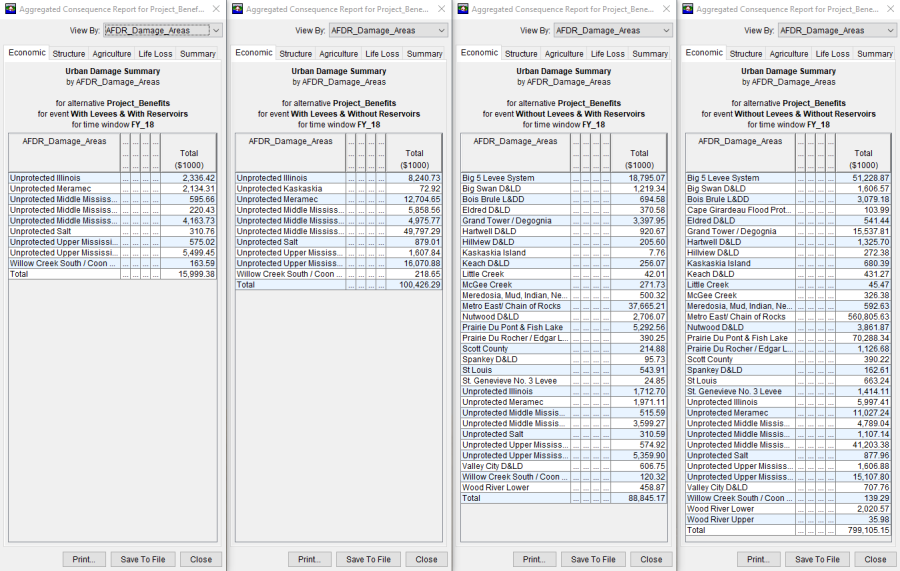
You’ll need results from four HEC-FIA computes, representing all combinations of levee and reservoir presence:
| D_{OBS}=\textsf{total damage with both reservoirs and levees (regulated or observed)} |
| D_{WOL}=\textsf{total damage with reservoirs but no levees (regulated without levees)} |
| D_{WOR}=\textsf{total damage with levees but no reservoirs (unregulated)} |
| D_{WOP}=\textsf{total damage without reservoirs or levees (unregulated without levees)} |
These results are available in the Aggregated Consequences Report in HEC-FIA.
Only areas with damages are listed in the report. If a leveed area experiences no damage in a particular scenario, it won’t appear—but it must still be reported to Congress. Ensure all federal leveed areas are included in your final AFDR dataset, regardless of whether they saw damage.

Validating the Results Against Logical Constraints
Before proceeding, ensure the following constraints are satisfied:
| D_{OBS} \leq D_{WOP} |
| D_{OBS} \leq D_{WOR} \leq D_{WOP} |
| D_{OBS} \leq D_{WOL} \leq D_{WOP} |
If any constraints are violated:
- Start troubleshooting from the HEC-HMS alternative and continue through HEC-RAS.
- Check for instabilities in flow, bridge modeling, model linking, or lateral structures.
- Once corrected, recompute all four HEC-FIA alternatives and validate again.
If errors persist and you're confident in the regulated (observed) damage compute, incrementally adjust the other scenarios, assuming observed damages is correct.
Allocating FDR Between Levees and Reservoirs (Weighted Method)
Once your damage results are validated, allocate the total leveed area FDR between the levee and upstream reservoir(s).
Calculate Key Variables
The following equations represent how much each component (levee or reservoir) reduces damage, depending on whether it was assumed to be installed first or last.
Equation 1:
| R_{1}=D_{WOP}-D_{WOL} \quad \textsf{and} \quad R_{2}=D_{WOR}-D_{OBS} |
| L_{1}=D_{WOP}-D_{WOR} \quad \textsf{and} \quad L_{2}=D_{WOL}-D_{OBS} |
Where:
| R_{1}=\textsf{reservoir(s) in place first} |
| R_{2}=\textsf{reservoir(s) in place last} |
| L_{1}=\textsf{levee in place first} |
| L_{2}=\textsf{levee in place last} |
Compute Weighted Allocation Percentages
Use the values from above in Equation 2 to compute allocation weights for each levee.
Equation 2:
| W_{R}=\frac{R_{1}+R_{2}}{R_{1}+R_{2}+L_{1}+L_{2}} \quad \textsf{and} \quad W_{L}=\frac{L_{1}+L_{2}}{R_{1}+R_{2}+L_{1}+L_{2}} |
Where:
| W_{R}=\textsf{percentage of leveed area FDR allocated to all reservoirs} |
| W_{L}=\textsf{percentage of leveed area FDR allocated to the levee} |
Why this matters: Unlike the "precedence" approach, the weighted method provides a more equitable distribution by treating reservoirs and levees as a system working together.
Calculate Final FDR Allocations
Once the weighted allocation percentages are computed, allocate the the total FDR per leveed area using the following equations.
Equation 3:
| FDR_{T}=D_{WOP}-D_{OBS} \quad \textsf{and} \quad FDR_{R}=W_{R}*FDR_{T} \quad \textsf{and} \quad FDR_{L}=W_{L}*FDR_{T} |
Where:
| FDR_{T}=\textsf{total leveed area FDR to be allocated between reservoir(s) and the levee} |
| FDR_{R}=\textsf{total leveed area FDR to be allocated to all reservoirs} |
| FDR_{L}=\textsf{total leveed area FDR to be allocated to the levee} |
This should be done for each leveed area in the modeling domain. Even if the reservoirs weren’t designed specifically to protect a given leveed area, any incidental benefits they provide should still be included.
System-Wide Allocation in Large Watersheds
Ideally, reservoir holdouts should be routed all the way downstream through connected watersheds—even across district and division boundaries.
- Coastal watersheds may already include this routing in their setups.
- Inland systems may require coordination between districts to ensure complete attribution.
The table below illustrates how upstream reservoirs (e.g., from the Missouri and Upper Mississippi Rivers) contribute to FDR in leveed areas on the Middle Mississippi River.
Leveed Area | Damage Reach | State | Overtopping | FDR Ratio (%) | FDR for Structures | |||
|---|---|---|---|---|---|---|---|---|
OBS | WOR | Levee | Reservoirs | Levee | Reservoirs | |||
Wood River | St. Louis | IL | No | No | 100 | 0 | $701,791,323 | $0 |
Metro East | IL | No | No | 41 | 59 | $11,591,977,427 | $0 | |
St. Louis | MO | No | No | 83 | 17 | $193,485,623 | $0 | |
Prairie Du Pont | IL | No | No | 59 | 41 | $579,635,484 | $0 | |
Columbia | IL | No | Yes | 95 | 5 | $9,070,609 | $12,833,648 | |
Harrisonville | IL | No | Yes | 100 | 0 | $63,370,286 | $43,139,736 | |
Festus–Crystal City | MO | No | No | 100 | 0 | $105,204,862 | $0 | |
Prairie Du Rocher | Chester | IL | No | Yes | 65 | 35 | $21,234,347 | $11,452,269 |
Ste. Genevieve | MO | No | No | 100 | 0 | $8,514,816 | $0 | |
Kaskaskia Island | IL | No | Yes | 82 | 18 | $10,167,674 | $502,841 | |
Bois Brule | MO | No | Yes | 100 | 0 | $56,310,769 | $12,524,954 | |
Grand Tower | Thebes | IL | No | Yes | 100 | 0 | $85,443,891 | $18,054,731 |
Big 5 (East Cape) | IL | No | No | 100 | 0 | $175,018,154 | $0 | |
Cape Girardeau | MO | No | No | 100 | 0 | $45,783,854 | $0 | |
Allocating FDR Among Multiple Reservoirs
After determining how much total FDR is allocated to reservoirs, you must assign those benefits to individual upstream reservoirs.
Flow-Based Holdout Method (Recommended)
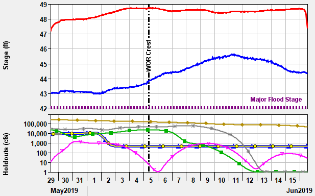
Correlate the peak stage date and time from the unregulated HEC-RAS simulation to the holdouts from the HEC-ResSim simulation for the respective damage reach gage locations. Then use the time slice (time of peak flow) of holdouts per damage reach to determine the proportion of the reservoir FDR for each damage reach. The figure below is an example plot showing peak stages plotted with holdouts from several upstream reservoirs.

Use the following equation to compute percentage contributions for each reservoir.
Equation 4:
| h_{A} = \frac{H_{A}}{\Sigma H} |
Where:
| h_{A}=\textsf{holdout for reservoir A as a percentage of the total holdouts of all reservoirs} |
| H_{A}=\textsf{holdout for reservoir A as a flow (cfs)} |
| \Sigma H=\textsf{summation of all reservoir holdouts for the damage reach area} |
Set negative holdouts to zero. Reservoirs that were evacuating storage do not receive FDR credit.
Alternative Method: Manual Allocation (Legacy Method)
If your district has predefined splits for reservoirs, those percentages can be applied instead. However, using real-time holdout data from HEC-ResSim is the preferred engineering method. If you're still relying on legacy methods, it's strongly recommended to transition to the holdout-based approach.