HEC-FIA Setup for Holdouts Compute
Computing AFDR using the HEC-FIA holdouts method allows you to process everything in one alternative using a CWMS forecast. This approach not only calculates total damages reduced but also apportions those reductions to reservoirs and levees.
As covered in Selecting an Approach and CAVI Setup, the holdouts method requires inundation data from two HEC-RAS alternatives—the regulated and unregulated events—and can also use HEC-ResSim holdout records to distribute damages among multiple reservoirs.
Setting up a holdouts-based FDR compute in HEC-FIA goes beyond the typical CWMS setup. This section walks you through the key steps using the Grid Holdouts Inundation Configuration (IC)—a simplified method that does not require importing HEC-RAS cross sections into HEC-FIA.
Model Naming Matters
Before diving into the setup, remember: naming conventions for model elements and HEC-DSS records must be consistent across HEC-RAS, HEC-FIA, and HEC-ResSim. Naming connects spatial elements (e.g., reservoirs, CCPs, levees) with time series data.
Boundaries
To meet federal reporting requirements, reservoir benefits must be reported by state. If your watershed spans multiple states, import a state boundary shapefile into HEC-FIA. This lets you break down results by state within the reports.
Storage Areas (Levees)
In grid-based FDR computes, storage areas serve one purpose: identifying leveed areas and the structures they protect.
Workflow:
- Export 1D/2D storage areas from HEC-RAS geometry via RAS Mapper.
- Import into HEC-FIA via the Storage Areas node.
- In the Import Storage Areas dialog:
- Mark which polygons are leveed areas.
- Optional: Populate the RiverName and CorpsPrj attributes.
If the without-levee compute misidentifies the river channel (e.g., in sinuous systems), explicitly set the RiverName to ensure proper querying of in-channel WSEs.

Reservoirs
To allocate damages to individual reservoirs, import a reservoir shapefile into HEC-FIA:
- The shapefile must include a field with reservoir names matching those in HEC-ResSim.
- The polygons are display-only; they do not affect calculations.
- Each reservoir must correspond to a FLOW-HOLDOUT time series in the .dss file.
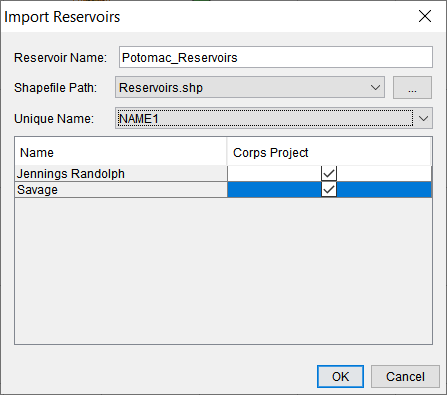
The figure below shows an example of the Import Reservoirs dialog in HEC-FIA.
The figure below shows an example of two holdout records for the Alexandria CCP. The holdout time series computed by HEC-ResSim for each reservoir at the CCP has a C Part of FLOW-HOLDOUT-<Reservoir Name>.

Stream Alignment
The stream alignment is critical in without-levee computes—it determines where structures query in-channel depths.
- If one exists, verify it's centered in the channel.
- If one does not exist, import the HEC-RAS centerline to serve as the alignment.
Holdout Areas (HOAs)
Holdout Areas (HOAs) are polygon shapefiles that define where damages reduced at structures are apportioned to reservoirs. All structures in an HOA use the same holdout ratio from the associated Common Computation Point (CCP).
Workflow:
- Export the full model extent (bounding polygon) from HEC-RAS using RAS Mapper.
- Use GIS to divide into HOAs based on judgment:
- Split near gages, confluences, or routing transitions.
- Consider hydrograph attenuation—less attenuation means you can group larger HOAs.
In the figure below, the damages reduced at structures in HOA 1 are awarded based on the flow holdouts computed in HEC-ResSim at CCP 1. Therefore, RES A is awarded all the damages reduced. Conversely, damages reduced at structures in HOA 2 is divided among both reservoirs based on the flow holdouts at CCP 2.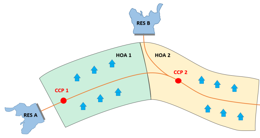
Use only a few HOAs if possible. For single-reservoir watersheds, one HOA is enough.
The figure below is an example of how you can set up HOAs for a small two-reservoir system. The HOAs each have an associated CCP (red dot). The two upstream reservoirs each have a CCP and associated holdout area to which only they contribute. Moving downstream, HOAs are broken up where changes in the system occur that impacts routing. 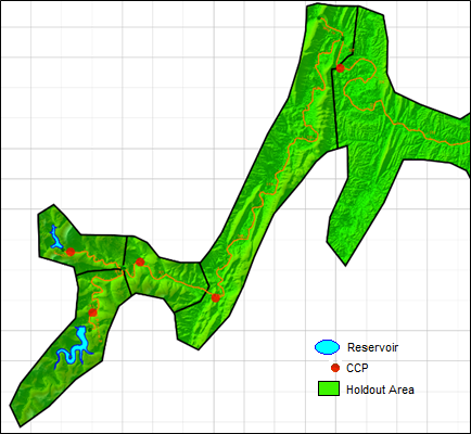
Each HOA must be linked to a CCP. Name HOAs after gages or HEC-ResSim junctions for clarity.
Common Computation Points (CCPs)
CCPs are shapefile points representing locations where HEC-ResSim holdout data is queried to apportion damages.
Workflow:
- Export CCPs from HEC-ResSim (via the Watershed Module).
- Use GIS to filter CCPs to just those needed (one per HOA).
- Each CCP:
- Must have a name field matching a HEC-ResSim junction.
- Must be downstream of a reservoir with flow holdouts available.
In HEC-FIA:
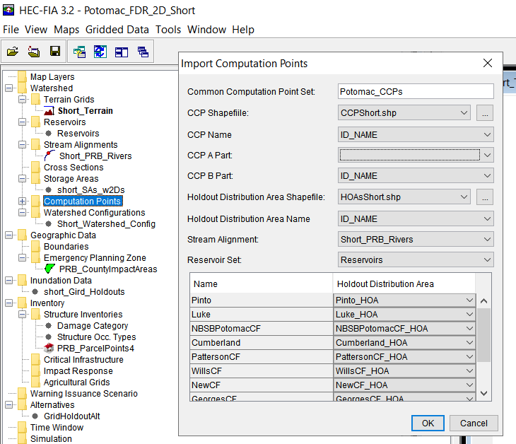
- Import CCPs using the Import Computation Points dialog.
- Link each CCP to:
- Its associated HOA
- The stream alignment
- The reservoir set
The figure below shows an example of this process.
Watershed Configuration
Pull everything together by creating or updating the Watershed Configuration to include:
- Stream alignment
- CCPs
- Reservoirs
This setup forms the backbone of your Holdouts Inundation Configuration.
Inundation Configuration: Holdout Grids
The Holdout Grids Inundation Configuration can now be used to compute AFDR. This type of configuration uses maximum depth rasters from HEC-RAS and flow holdout records from HEC-ResSim.
To create a new configuration:
- Define a new Event.
- Link to the HEC-RAS output depth grids (.vrt files)
- Check the option to Use HEC-ResSim Calculated Holdout Time Series
- Select flow holdout time series from HEC-ResSim:
- Specify the output .dss file
- Select the E Part
- Select the Output F Part
- If using manual overrides instead, uncheck Use HEC-ResSim Calculated Holdout Time Series.
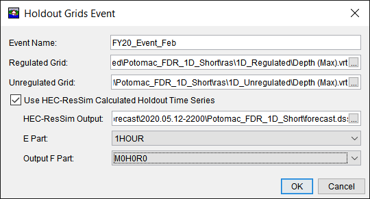
By selecting .vrt files, HEC-FIA will automatically reference multiple terrain tiles. This method is preferred for querying depths.
Final Steps
The final steps for the HEC-FIA model setup are:
- Create a new Alternative using the new IC.
- Set the time window.
- Create and run a Simulation.
Once computed, review results by right-clicking the simulation and selecting one of the two report options. More information regarding the interpretation of these results can be found in Analyzing Consequence Results.