Computing Damages Reduced for the Detailed Approach
When computing FDR using the detailed approach, individual damage computes are processed to calculate damages reduced, then damages reduced are apportioned to reservoirs and levees. This section describes the process as summarized:
- Extract damage results from individual damage computes
- Ensure damage results do not violate constraints
- Compute reservoir and levee weights for each levee
- Compute weighted average FDR for each levee
- Compute allocation percentages for individual reservoirs
- Compute FDR for individual reservoirs.
Computing Total and Levee Flood Damages Reduced
Results from four individual HEC-FIA damages computes representing the various with- and without-reservoir and levee scenarios, are required. Results from each of these scenarios are represented with notation:
| D_{OBS}=\textsf{total damage with reservoirs and with levees (regulated or observed)} |
| D_{WOL}=\textsf{total damage with reservoirs and without levees (regulated without levees)} |
| D_{WOR}=\textsf{total damage without reservoirs and with levees (unregulated)} |
| D_{WOP}=\textsf{total damage without reservoirs and without levees (unregulated without levees)} |
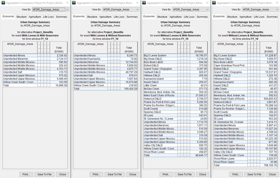
You can extract these results from the Aggregated Consequences Report in HEC-FIA for each alternative. Figure 1 shows the aggregated reports from each of the individual computes. Only the boundary areas that have damages are reported in the aggregated reports. In other words, the list of boundaries ("AFDR_Damage_Areas" in this example) is larger in the more damaging events. Understanding this is critical when extracting data out of the reports, since all leveed areas need to be reported in the AFDR report to Congress (even if there were no FDR for that leveed area).

Since this method uses a weighted average to compute FDR, the results for each damage area or boundary should be checked to ensure the following constraints are met:
| D_{OBS} \leq D_{WOP} |
| D_{OBS} \leq D_{WOR} \leq D_{WOP} |
| D_{OBS} \leq D_{WOL} \leq D_{WOP} |
Any violation of the above constraints should be remedied by verifying each of the previous models in the sequence are set up appropriately. This verification starts with the HEC-HMS alternative and continues through HEC-RAS to uncover any errors in the sequence for each of the four scenarios, starting with the observed (regulated) event. Issues are often uncovered in model linking, low-flow or high flow instabilities, bridges, confluences, lateral structures, etc.
Once you verify the results, each of the HEC-FIA alternatives are recomputed and checked against the constraints again to determine if there are any program errors. If all results are validated and there are still violations of the constraints, corrections to the results need to be performed to continue with the analysis. The variables should be corrected for the constraints by going left to right. The modeler should assume observed damages are correct and increase the variables going the right accordingly.
Once the constraints are checked (and corrected if necessary), the total FDR for each leveed area needs to be allocated to the reservoir(s) and the leveed area. The allocation method is based upon a weighted calculation, with the weights computed from both levee and reservoir precedence. Equation 1 lists the formulas of the four variables needed based upon precedence to determine the weighted percentage of allocation of the total FDR to reservoirs and levees.
Equation 1:
| R_{1}=D_{WOP}-D_{WOL} \quad \textsf{and} \quad R_{2}=D_{WOR}-D_{OBS} |
| L_{1}=D_{WOP}-D_{WOR} \quad \textsf{and} \quad L_{2}=D_{WOL}-D_{OBS} |
Where:
| R_{1}=\textsf{reservoir(s) in place first} |
| R_{2}=\textsf{reservoir(s) in place last} |
| L_{1}=\textsf{levee in place first} |
| L_{2}=\textsf{levee in place last} |
Using the precedence method to allocate FDR gives the majority of FDR to the reservoir or levee. Instead, the weighted average allocation method more equitably divides FDR among levees and reservoirs. The assumption is that the upstream reservoirs and the levee act as a system to provide protection, and the weighted allocation formula computes the proportion of the reservoirs versus the levee had within the boundary of the leveed area. Equation 2 describes how to compute the weights for both levees and reservoirs. Theses weights should be computed for each levee.
Equation 2:
| W_{R}=\frac{R_{1}+R_{2}}{R_{1}+R_{2}+L_{1}+L_{2}} \quad \textsf{and} \quad W_{L}=\frac{L_{1}+L_{2}}{R_{1}+R_{2}+L_{1}+L_{2}} |
Where:
| W_{R}=\textsf{percentage of leveed area FDR to be allocated to all reservoirs} |
| W_{L}=\textsf{percentage of leveed area FDR to be allocated to said levee} |
Once the weighted allocation percentages are computed, the total FDR per leveed area can be allocated. The total FDR for each leveed area and the allocated FDR for the reservoir(s) and levee(s) are calculated using Equation 3.
Equation 3:
| FDR_{T}=D_{WOP}-D_{OBS} \quad \textsf{and} \quad FDR_{R}=W_{R}*FDR_{T} \quad \textsf{and} \quad FDR_{L}=W_{L}*FDR_{T} |
Where:
| FDR_{T}=\textsf{total leveed area FDR to be allocated between reservoir(s) and leveed area} |
| FDR_{R}=\textsf{total leveed area FDR to be allocated to all reservoirs} |
| FDR_{L}=\textsf{total leveed area FDR to be allocated to said levee} |
This allocation methodology is applied to each federal levee downstream of USACE reservoirs, even if the reservoirs do not explicitly operate for the damage reach in which the leveed area resides. If the reservoir does not operate for the damage reach or the leveed area, these FDR allocations are considered to be incidental benefits of having flood reduction reservoirs upstream.
Ideally, these reservoir holdouts are routed through all watershed systems downstream to the ultimate outlet, the ocean. For coastal watersheds, this might already be a part of the AFDR process. For inland watersheds, this requires handing off reservoir holdouts and regulated and unregulated flows across district and division boundaries to properly attribute the systematic FDR for all reservoirs and levee systems in the greater watershed. The table below provides an example of the FDR allocated for leveed areas along the Middle Mississippi River due to the upstream reservoir holdouts (Upper Mississippi River and Missouri River watersheds).
Example of Computing Flood Damages Reduced for Levees in a Large System
Leveed Area | Damage Reach | State | Overtopping | FDR Ratio (%) | FDR for Structures | |||
OBS | WOR | Levee | Reservoirs | Levee | Reservoirs | |||
Wood River | St. Louis | IL | No | No | 100 | 0 | $701,791,323 | $0 |
Metro East | IL | No | No | 41 | 59 | $11,591,977,427 | $0 | |
St. Louis | MO | No | No | 83 | 17 | $193,485,623 | $0 | |
Prairie Du Pont | IL | No | No | 59 | 41 | $579,635,484 | $0 | |
Columbia | IL | No | Yes | 95 | 5 | $9,070,609 | $12,833,648 | |
Harrisonville | IL | No | Yes | 100 | 0 | $63,370,286 | $43,139,736 | |
Festus–Crystal City | MO | No | No | 100 | 0 | $105,204,862 | $0 | |
Prairie Du Rocher | Chester | IL | No | Yes | 65 | 35 | $21,234,347 | $11,452,269 |
Ste. Genevieve | MO | No | No | 100 | 0 | $8,514,816 | $0 | |
Kaskaskia Island | IL | No | Yes | 82 | 18 | $10,167,674 | $502,841 | |
Bois Brule | MO | No | Yes | 100 | 0 | $56,310,769 | $12,524,954 | |
Grand Tower | Thebes | IL | No | Yes | 100 | 0 | $85,443,891 | $18,054,731 |
Big 5 (East Cape) | IL | No | No | 100 | 0 | $175,018,154 | $0 | |
Cape Girardeau | MO | No | No | 100 | 0 | $45,783,854 | $0 | |
Allocating Flood Damages Reduced Among Reservoirs
Once the FDR for each levee is computed, the next step is to allocate the total reservoir FDR to individual reservoirs in the system. If there is only one reservoir within the watershed, then all calculated reservoir FDR is attributed to the single reservoir. However, if there are multiple reservoirs, you must allocate the reservoir FDR to each respective upstream reservoir based upon the holdouts from HEC-ResSim.
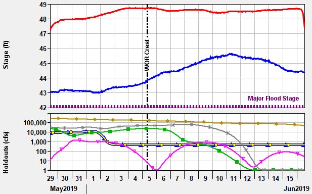
The peak stage date and time from the unregulated HEC-RAS simulation should be correlated to the holdouts from the HEC-ResSim simulation for the respective damage reach gage locations. This time slice (time of peak flow) of holdouts per damage reach gage location is then used to determine the proportion of the reservoir FDR for each damage reach. Figure 2 is an example of the ???

Once the reservoir holdouts are referenced, the holdouts are converted to percentages. The reservoir allocation of the FDR for the damage reach area is simply the reservoir holdout divided by the sum of the positive holdouts. Negative holdouts are assumed to be zero. Reservoirs that might be evacuating storage are not assigned any FDR. Equation 4 is used to determine the allocation percentages for all reservoirs in each damage reach.
Equation 4:
| h_{A} = \frac{H_{A}}{\Sigma H} |
Where:
| h_{A}=\textsf{holdout for reservoir A as a percentage of the total holdouts of all reservoirs} |
| H_{A}=\textsf{holdout for reservoir A as a flow (cfs)} |
| \Sigma H=\textsf{summation of all reservoir holdouts for the damage reach area} |
Note:
All negative flow holdouts must be set to zero for Equation 4 (i.e., Hi≥0).
Alternatively, districts and divisions may have simplified legacy methods for allocating FDR for reservoir systems. These predefined allocation percentages can be applied to the total FDR in each damage reach. However, utilizing reservoir holdouts to compute each of the reservoir's FDR per damage reach is the correct engineering methodology. You should strongly consider discontinuing the use of legacy methods and replace it with the proper holdout routing FDR allocations.