Creating a Stream Alignment for the CAVI
The objective of this tutorial is to guide you through creating and verifying a stream alignment. The stream alignment is used by the CAVI as the foundation for drawing the shared model schematic in its map window(s). It is important to have a good stream alignment for model development, integration, and display.
Some characteristics of a good stream alignment are:
- Each unique river or stream in the stream alignment is represented by a single continuous line.
- Each stream has a unique name - preferably, its real name. For example, the Mississippi River should be named Mississippi or Mississippi River, not Stream 1 or MissReach1.
- The streams in the stream alignment encompass every modeled reach, stream gage, control point, and project (reservoir, levee, or control structure) in the watershed.
- Each stream has as many points defining it as are needed to adequately describe its shape.
Steps to Follow to Create the Best Stream Alignment
- Obtain or prepare a polyline shapefile representing the rivers throughout your watershed.
- Remember, the streams/rivers in this shapefile need to encompass all reaches of all the models that are planned to be used in the CWMS watershed.
- This shapefile may be generated by hand, by the geo-tools of one or more of the models, or by some other source or process.
- Once you have a polyline shapefile of the rivers and streams, use a GIS software application (like ArcGIS) to edit the shapes. Some of the things to address:
- If a river is broken into multiple polylines, merge the pieces into one. Do this for every river in the shapefile. When finished, you should have a single polyline with a unique name for each river or stream in the shapefile (no duplicated names).
- Next, generalize the polylines in your shapefile. Use a tolerance value appropriate to your map units and your models. For example, if the streams were created from a 30m DEM, a 1m tolerance is not going to have much impact, but a 10-15m tolerance will. Also, use some form of recent imagery or background maps to help you determine the right tolerance to use so that you don't remove too much detail, as this could affect how one or more of the models display in the CAVI.
- By generalizing, you will reduce the number of points that define each stream. When the stream alignment is overly detailed, the CAVI's response time for any map-based action can slow down appreciably.
- By generalizing, you will reduce the number of points that define each stream. When the stream alignment is overly detailed, the CAVI's response time for any map-based action can slow down appreciably.
- Import the stream alignment from the completed shapefile. In the illustrations below, HEC-ResSim was used to create and edit the stream alignment. The same operations can be performed from the CAVI.
- First, create a new watershed in HEC-ResSim (File → Create New Watershed).
- Specify the required information – Watershed Name, Watershed Location, Units, and Time Zone. The units and time zone selections should match the models planned for the CWMS watershed.
- Using a file browser, copy the streams shapefile to the watershed's maps folder - you don't have to close the watershed or HEC-ResSim to do this.
- Copy the subbasin shapefile to the watershed's maps folder, if you have access to one.
- Use the Layers editor (View → Layers) to add these maps to the watershed (Maps → Add Map Layer).
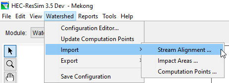
- Import the stream alignment into the watershed. From HEC-ResSim's Watershed menu, select Import → Stream Alignment.

- Alternately, from the Setup tab within the CAVI, select Stream Alignment → Import from the Watershed menu.

- Select the streams shapefile that you added to the watershed. In the name field, select the attribute that will uniquely identify each stream, this is usually the "name" attribute.
- Determine if the list of streams is correct. All the checkboxes in the Import column should be checked. If for any reason you do not want to import some of the streams into your stream alignment, uncheck those streams in the table. Then, click Import.
- Review the streams in your stream alignment that is displayed in your map space - take particular note of the stream stationing. Each stream's station 0 should be at the mouth of the stream (the downstream end).
- If all the streams came in backward, repeat steps f-h, but this time, click the Reverse Direction button and check the option to Replace Existing Stream Elements before you click Import. If only a few streams are backward, use the stream alignment tool, then right-click on each stream and select Reverse Direction.
- If all the streams came in backward, repeat steps f-h, but this time, click the Reverse Direction button and check the option to Replace Existing Stream Elements before you click Import. If only a few streams are backward, use the stream alignment tool, then right-click on each stream and select Reverse Direction.
4. Next, ensure the streams are properly connected.
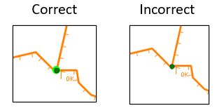
- At each stream confluence (called a stream junction) where two or more streams connect, the stream alignment should show a dark green dot surrounded a light green halo. The light green halo is the visual representation of a stream junction (a connection) in the stream alignment. If you only see a dark green dot, the streams are NOT connected.

- If there are confluences that do not have the light green halos, use the stream alignment tool as follows to connect the reaches.
- Zoom in on the confluence.
- Select the stream alignment tool, then double-click on the stream that ends at the confluence (the tributary). This will cause the stream to turn red and the vertices to turn blue.
- If you can see space between the downstream-most vertex of the selected reach and the stream it should be connected to, drag that vertex to where it should be connected to the other stream. If you cannot see space between the streams, drag the vertex slightly away from the junction and then back to where you found it.
- When you release the mouse button, you will get a dialog like the one below asking if you want to connect the streams - select Yes. The green dot should now have the halo.

- Repeat this process until all the confluences have bright green halos.
- Save the watershed.
- If you used HEC-ResSim to create the stream alignment, close HEC-ResSim and continue to step 6.
- If you created the stream alignment within the CAVI, skip to step 7.
- At each stream confluence (called a stream junction) where two or more streams connect, the stream alignment should show a dark green dot surrounded a light green halo. The light green halo is the visual representation of a stream junction (a connection) in the stream alignment. If you only see a dark green dot, the streams are NOT connected.
6. Import the stream alignment (the HEC-ResSim model) into the CAVI watershed.
- Open the CAVI (either HEC-RTS or CWMS).
- Create a new watershed: File → New Watershed.
- Fill out all needed information (ensure that the unit system, time zone and coordinate system match your models).
- Import the HEC-ResSim watershed model. This will bring the stream alignment into the CAVI.
- It will also copy the maps from the HEC-ResSim maps folder, but you will need to add them to the watershed display separately.
- It will also copy the maps from the HEC-ResSim maps folder, but you will need to add them to the watershed display separately.
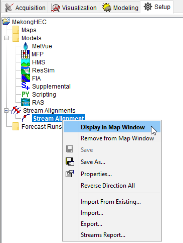
7. Now, display the stream alignment in the CAVI by expanding Stream Alignments in the watershed tree. From the Setup module, click on Stream Alignment and select Display in Map Window.
