Download PDF
Download page How the Calibration Works.
How the Calibration Works
HEC-MetVue uses a geometric algorithm as opposed to most methods that rely on statistical methods to attempt a radar calibration. First, the program determines which radar grid cell center points reside in each of the triangles formed by the rain gage TIN. It then uses the measurement values of the rainfall TIN, which are defined at the triangle vertexes, to adjust all the radar grid cells within that triangle using a double interpolation technique. Not only does this give a calibrated radar image that matches the TIN of the rainfall data at known points, it also preserves the relative, albeit adjusted, intensity values of the radar where no gage exists. Unlike statistical means which tend to diminish the radar measurement values from their highs and lows, this method does not either blur the image or become unstable.
There are limitations the application of HEC-MetVue geometric algorithms. First, hail which confuses the radar and shows a very high return and thus very high rainfall, may not be accurate since the radar image no longer is representative of the rainfall itself and now represents a non-linear relation between the radar return and actual rainfall. Secondly, rain events with supercell storms may not calibrate well due to the fact that storms can completely miss the gages and no bias can be applied. For example, there is no meaningful way a radar image that has reported zero rainfall at the gage and in the radar bin above the gage can be adjusted since no difference is apparent. Although this may be a problem from a mathematical perspective, supercell storms are usually so localized that they do not cause problems on larger reservoirs. Also, at the worst, no bias is applied and the supercell is the same size as before. Third, the algorithms have not been tested where orographic effects from mountains influence precipitation, but the expectation is that it will perform very well as long as the rain gages are well distributed with respect to elevation.
There are some issues with a rain gage TIN having a rainfall value of zero at a gage location while the radar value at that vertex is non-zero and vice versa. When this happens, there is a point where the computation method must switch from one technique to another. Whenever the ratio of the radar to the rainfall exceeds 3.0, the algorithms switch to an additive approach as opposed to a ratio approach to adjust the radar image. This algorithm determination evaluation occurs independently for each of the rainfall TIN gage location/radar estimation combinations in the dataset.
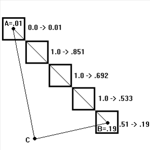
Below is an example of the calibration. To simplify the computations, consider the 5 grid cells evenly spaced along a line between A and B where the points A and B make up two of the corner points of a triangle of the precipitation TIN. The simplification comes from the fact that since the grid cells are precisely on a line between A and B, the third point of the triangle, Point C, has no weight.

Point | Rain | Radar Estimate | Delta | Ratio |
A | 0.01 | 0.00 | 0.01 | ∞ |
B | 0.19 | 0.51 | -0.32 | 0.3725 |
Weighting a point based on how far it is from Point A and B respectively with point 1 being the center of the radar bin on top of point A and point 5 being the radar bin on top of point B:
Point weight | 1 | 2 | 3 | 4 | 5 |
Weight A | 1.00 | 0.75 | 0.50 | 0.25 | 0.00 |
Weight B | 0.00 | 0.25 | 0.50 | 0.75 | 1.00 |
The ratio of Point A (.01 / 0) is greater than 3. Additive weighting will be used from this point. The ratio of Point B (.3725) is less than 3. The ratio method will be used from this point.
When additive weighting for a point is used, its ratio is 1. When ratio weighting for a point is used its difference is 0. Given this and the generalized equation shown below and ignoring point C yields:
adjZ = origRadarZ * (ratioA * weightA + ratioB * weightB) + diffA * weightA + diffB * weight
From the above table, ratioA=1, ratioB=0.3725, diffA=0.01 and diffB=0.00. Again, from the above rules, ratioA was set 1 for additive weighting and diffB was set to 0 for ratio weighting. Then, the following is a summary of the adjusted radar bins.
Radar Bin | Original rain | Original Radar | Adjusted Radar |
1 | 0.01 | 0.00 | 0.01 |
2 | 1.00 | 0.851 | |
3 | 1.00 | 0.692 | |
4 | 1.00 | 0.533 | |
5 | 0.19 | 0.51 | 0.19 |