Download PDF
Download page Pipe Network - Geometry.
Pipe Network - Geometry
Pipe network geometries are defined by Nodes (represented by a points layer) and Conduits (represented by a polyline layer), and their associated attributes. Nodes provide the connections between multiple Conduits at junctions, provide connections from the pipe network to 1D and 2D surface elements (via drop inlets or daylighting pipes such as culverts), and are where external boundary conditions can be introduced to the system.
HEC-RAS Pipe Networks are Geospatial
Unlike many other stormwater modeling software which rely on stick model representations of the geometry, HEC-RAS Pipe Network geometries are fully geospatial. That means when adding pipe network nodes and conduits in HEC-RAS, they should reflect the true georeferenced locations and dimensions.This chapter starts by describing how to enter, edit, and import pipe network geometry in HEC-RAS Mapper. Then, details about what the Node and Conduit attributes represent and how they are used to create Pipe Networks is covered.
Creating Pipe Network Geometry
Pipe network geometries can be created by drawing Nodes, drawing connecting Conduits and defining the attributes of each in their respective attribute tables. All geometry creation and editing for pipe networks is done from HEC-RAS Mapper.
Creating pipe network geometry can also be done via a shapefile importer that allows users to import georeferenced features and map the corresponding attributes (inverts, conduit shape, size, roughness, etc.) to the appropriate HEC-RAS geometry fields. In addition to the shapefile importer, an importer is available to assist modelers in converting existing US Environmental Protection Agency's Storm Water Management Model (EPA-SWMM) elements from the *.inp file into HEC-RAS pipe networks.
Drawing Nodes and Conduits
Both Nodes and Conduits can be added to the model geometry using the standard editing tools within HEC-RAS Mapper. The preferred sequence for creating a new pipe network in HEC-RAS is as follows:
- Add Nodes to the Pipe Network geometry: Nodes should be added at the junctions of conduits (where two or more conduits meet), at locations where the pipe network connects to surface elements (drop inlets or culvert openings), and where boundary conditions (inflow hydrographs, downstream stage or normal depth) will be applied. While it is possible to create conduits prior to creating endpoint nodes, it is preferable to add nodes first and then add conduits. Added in this order, the conduits will snap directly to the nodes and populate the connectivity attributes for both nodes and conduits.
- Add Conduits to the Pipe Network geometry: Conduits should be added, connecting all the nodes to create a pipe network. Note that every Conduit must have a Node on both ends.
- Populate Node and Conduit Attributes: Once the features of the pipe network are added, the required attributes for Nodes and Conduits then should be populated by editing their respective Attribute Tables in HEC-RAS Mapper.
The process for drawing Nodes and Conduits is very similar. In HEC-RAS Mapper, begin an editing sessions, select the desired layer to edit in the tree view, and select the Add New tool  . Nodes can then be drawn on the map with a single click as shown below:
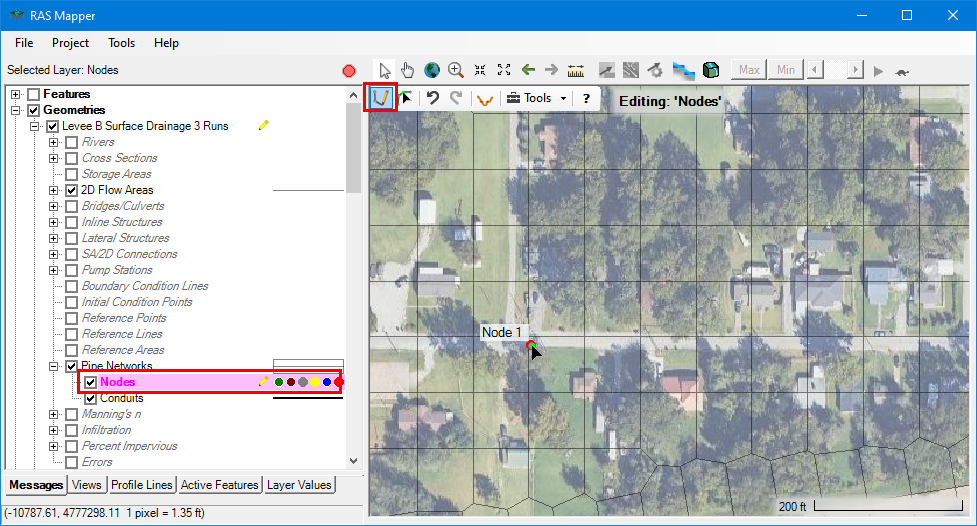
When a node is added, a default name is provided that can be changed later from the node attribute table. After nodes have been added, their location can be moved using the Select/Edit Tool ![]() .
.
After nodes are placed, conduits should be drawn from upstream node to downstream node.
Draw Conduits Upstream to Downstream
Though not a computational requirement, drawing conduits upstream to downstream can make for easier interpretation of results and model review. The direction of the conduit lines impact where entrance and exit loss coefficients are applied, and what Node Type is assigned to the connected nodes.The direction of the conduits can be shown by turning on the Directional Arrows plot option as shown below: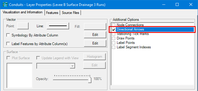
With nodes already drawn, drawing conduits is simple. To start drawing a conduit, single-click in the map window to place the upstream vertex and consecutive vertices, and double-click to finish. If cursor is inside of the snapping distance, the conduit vertex will automatically snap to the node as shown below.
A handy tool for editing conduits that have already been drawn, but not snapped to nodes, is the Snap Conduits to Nodes tool. This will snap the conduit ends to the closest node if any exists within a search radius around the first and last points of a conduit.
This tool can be accessed from right-clicking the conduits layer in the tree view as shown below. Accessing the option here will attempt to snap all nodes to conduits.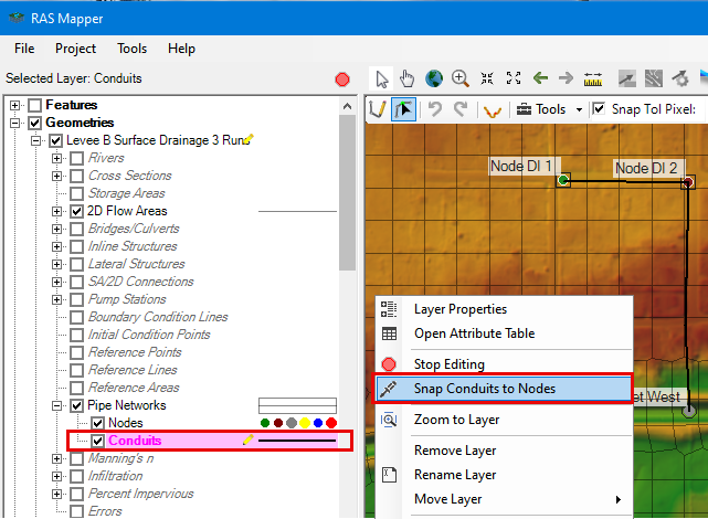
Individual conduits, or a selection of conduits can be snapped by right-clicking the conduit feature in the map view: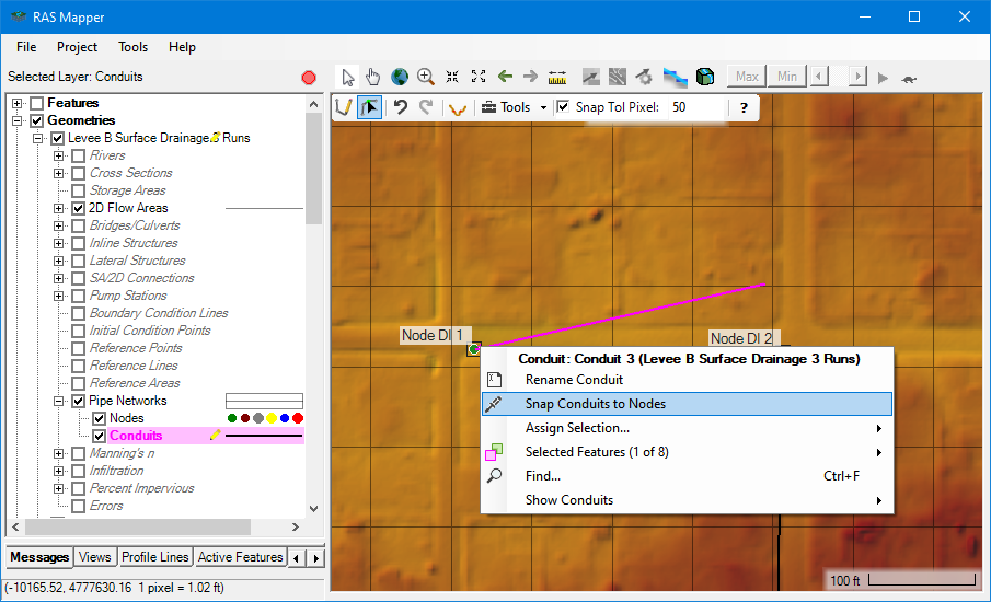
Conduit Speed Draw Mode
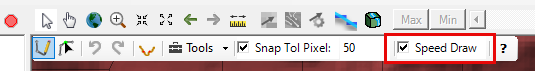
In order to help draw pipe networks more quickly, the Speed Draw mode automatically places nodes at the ends of newly finished conduits. To turn on Speed Draw mode check the box in the conduit editing tool bar, then nodes will be placed at the ends of each newly completed conduits if one does not exist there already.
Use 'Split Selected Feature' To Add Nodes to Existing Conduit
An existing conduit can be split using the Split Selected + Add Node tool. This tool is handy when additional drop inlets or manholes are desired to be placed on an existing conduit.
When Split the Selected tool is used on a conduit:
1) Two conduits will be created and attributed from the existing conduit's information
2) A node will be placed where the conduits are split and the elevation of the new node will be populated to maintain the slope of the existing conduit.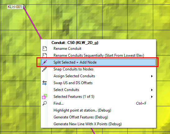
Tip
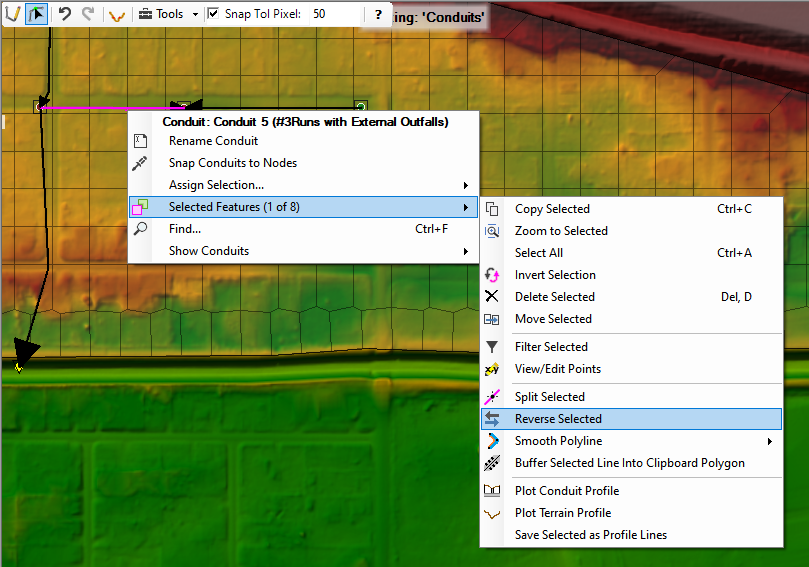
If a conduit has been drawn or otherwise entered with the wrong flow direction, it can be reversed by selecting it with the editing tools and right-clicking on the conduit. Then select Reverse Selected and all of the selected conduits will have their drawn direction reversed.
Importing Nodes and Conduits from GIS data
If existing GIS data is available for a stormwater system, the data can easily be imported to create a Pipe Network in HEC-RAS. This shapefile importer affords the flexibility to import geometry information from various sources such as utility maintenance files, design files, or exports from other pipe modeling software
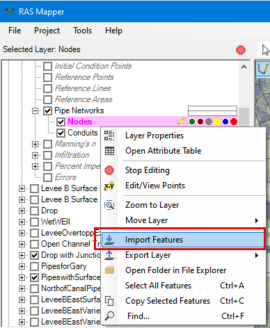
To import a shapefile or GeoJSON file begin, editing the geometry by right-clicking on the geometry or selecting the edit icon. Then right-click the layer in the tree view and select Import Features ![]() .
.
When the Feature Importer opens, Select the shapefile or GeoJSON file containing the node or conduit data in the Filename box. The features available for import will display in left panel and in the map panel of the dialog. The user can decide which features to import by selecting or unselecting them in the left panel.
The bottom panel allows for mapping the shapefile fields (show in the drop downs) to the required HEC-RAS conduit or node fields (shown in column headers). If the HEC-RAS required fields are not available from the imported shapefile, further populating of attribute tables will be required after import.
Importing Nodes and Conduits from EPA-SWMM Models
The U.S. Environmental Protection Agency's Storm Water Management Model (EPA-SWMM) is the most widely used stormwater software in world, and is also the backbone of many other popular stormwater modeling software suites. If a modeler has in existing EPA-SWMM based model, it's geometry can be brought into HEC-RAS to help create pipe networks.
In order to import EPA-SWMM geometries to HEC-RAS, the EPA-SWMM elements must be georeferenced in a known coordinate reference system.
One way to bring in EPA-SWMM geometry is to first export the SWMM geometry to a shapefile or GeoJSON file, and then import to HEC-RAS using the Feature Import tool discussed in the section above. This method give the user the opportunity to visualize and manipulate data in a GIS before importing it into an HEC-RAS pipe network. Many SWMM based models have an export capability built in, or GIS plugins are freely available in Quantum GIS to do perform the same task for a given *.inp file.
The other option for importing EPA-SWMM geometry is to use the Import SWMM Geometry tool from HEC-RAS Mapper to import the elements directly to Nodes and Conduits in HEC-RAS Mapper. This option requires fewer steps and is good for getting started with simple SWMM models that won't require much GIS editing.
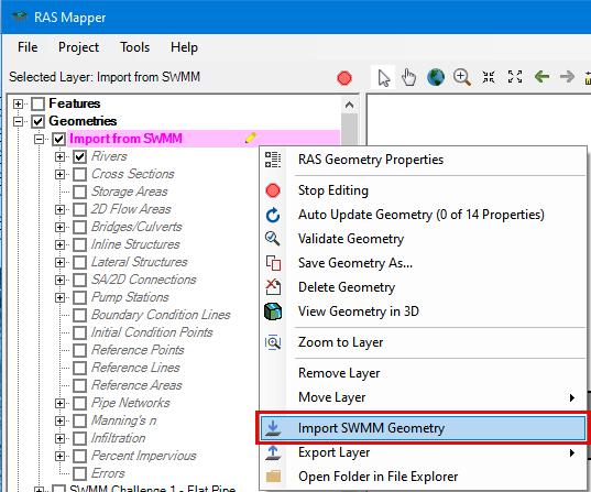
To import EPA-SWMM geometry directly to HEC-RAS nodes and conduits in RAS Mapper: Start an edit session on a new or existing geometry, Right-click the geometry and select Import SMM Geometry ![]() .
.
When Import SWMM Project Dialog launches, select the SWMM *.inp file you wish to import. Then select from the following options:
Merge Subcatchments Into Single 2D Area: When ON this option will import the SWMM subcatchments and merge them to a single HEC-RAS 2D Area. This option is useful when the SWMM subcatchments if the watershed are well delineated and when using their extents to model surface flooding is desired. THe accompanying Buffer Smooth Distance: is the buffer distance that will be applied to the subcatchment polygons to ensure they are overlapping, such that they can be merged into a single 2D Area.
Use Catchment Boundaries As Breaklines: When ON This option will import the SWMM subcatchment boundaries as breaklines for the 2D mesh in the RAS Model.
Remove Unconnected Nodes: When ON this option will omit SWMM nodes that are not connected the the network by an HEC-RAS compatible SWMM link such as a SWMM orifice or weir link.
Attributing Nodes and Conduits
Once the nodes and conduits are drawn, properly attributing them is the next step in characterizing the pipe network system. This section describes tools for viewing and editing pipe network attributes. For Details about what the Node and Conduit Attributes represent is covered in the Node Attributes and Conduit Attributes Sections.
The attributes for the nodes and conduits are viewed and edited exclusively in HEC-RAS Mapper by right-clicking the layer in the tree and and selecting Open Attribute Table ![]() .
.

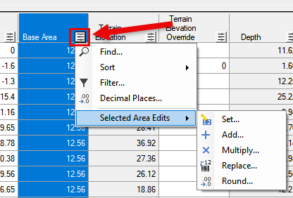
When an edit session is initiated on the layer and the attribute table is open, attribute values can be entered by hand, copy/pasting, or bulk edited by column using the column sort and edit tools. The column sort and edit tools are located at the top of each column ![]() and can be used to edit the selected values globally by setting them directly performing math on the values in the column as shown in the figure below.
and can be used to edit the selected values globally by setting them directly performing math on the values in the column as shown in the figure below.
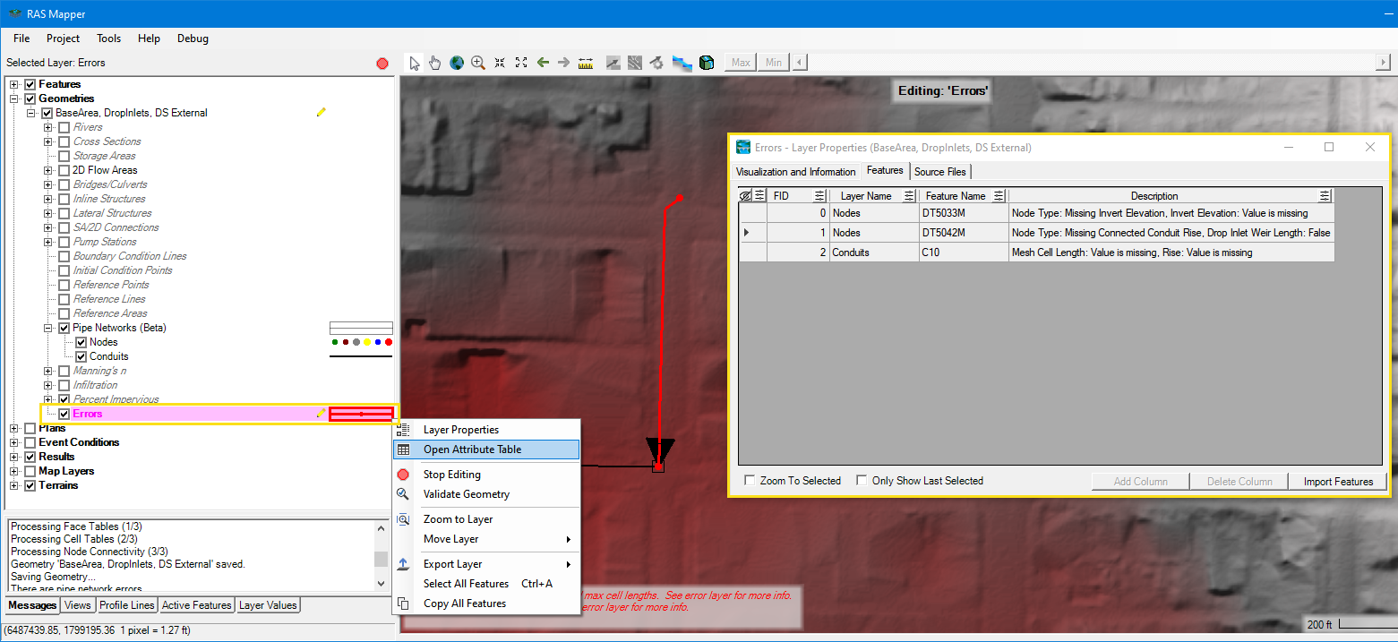
When values are missing or there is an issue with the input data, the attribute table will highlight in red the problem cells. The figure below shows an example of a Node attribute table where an Invert Elevation value is missing for the first row. In addition to the red Invert Elevation cell, the Node Type shows Error since the invert elevation is required to determine the Node Type. Finally the Node Status also provide an indication of the error: *Missing Invert Elevation*.
The second row has an Drop Inlet Elevation indicating a Drop Inlet is intended, but is missing the Drop Inlet Weir Length which is highlighted in red. The Node Status also indicates that there is an issue with the input data: *Missing drop inlet attributes*.

The Error Layer which appears at the bottom of the geometry while in an Edit Session shows which conduits and nodes have errors in the map window and provides details in the Error Layer attribute table.
Note
Some of the error checking in Pipe Networks is done on the fly during an edit session. However, other error checks are completed on the closure of an edit session since the Pipe Network connectivity must be recomputed. That said, if error messages still appear after input data was modified, try to cycle through an edit session.
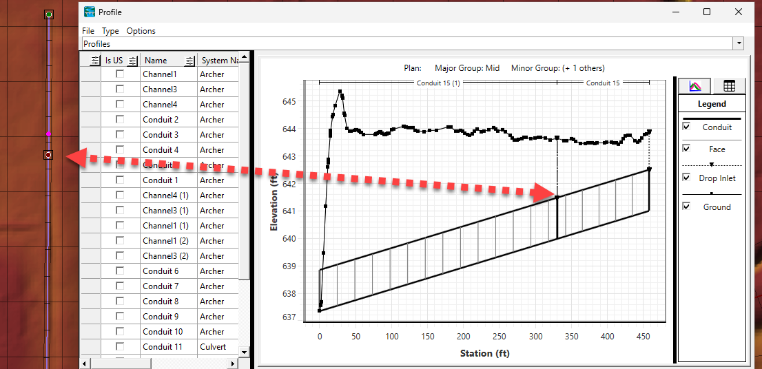
Use Profile Plot to Verify Geometry Attributes
Another useful tool when building and checking Pipe Network geometry is to plot the profile of the geometry. To do this, select the desired conduits to plot in the map window, then right-click and select Plot Conduit Profile for the selected conduits. As an alternative to selecting individual conduits, the video below shows some additional selection tools
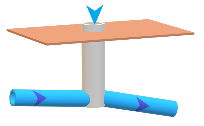
Pipe Network Mesh
Once Nodes and Conduits are drawn and attributed appropriately, a Pipe Network mesh will be created automatically and cell and face property tables will be computed when the edit session is closed. An algorithm places mesh faces placed based on the Cell Mesh Size attribute of the conduits, the Length of the conduits, and the the Base Area of the Node cells. Depending on the junction Base Area relative to the size of the incoming conduits, the junction cell will borrow portions of the connected conduits. This borrowing is intended to prevent the creation of very small cells at the junctions so the computation times are not limited by the small cells.
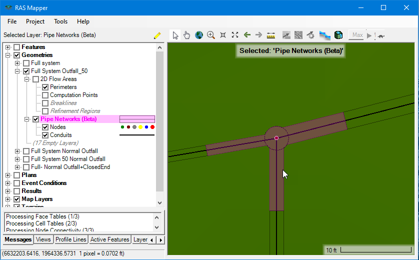
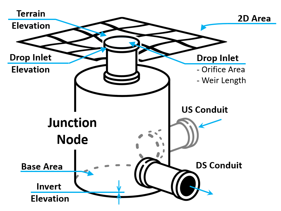
The pipe network mesh will be displayed in the map window of RAS mapper by default. Property tables for the cells and faces can be accessed by selecting the Pipe Networks Layer in the tree and right-clicking cells or faces in the map window. Below is an example of what the mesh cells look like where three conduits come together at a junction node. This node has a non-zero Base Area defined, giving it the circular shape seen. Also note that the node cell here is borrowing portions of the connected conduits.
Nodes
The pipe Nodes in HEC-RAS provide connections between conduits and other elements in the model. Nodes can represent a variety of physical structures (e.g., manholes, drop inlets, junction boxes, etc.) or they can represent no structure at all (e.g., daylighting pipes such as culverts). What a node represents is reflected in its attributes, its conduit connections, and its connection to 1D or 2D surface element. The combination of these conditions results in an automatically assigned Node Type which will be discussed further in the Node Attributes section.
Nodes should be placed at the end of all conduits and are used to model:
- Junction boxes or manholes between multiple conduits
- Locations where conduits change in size or slope
- Wet wells or other subsurface storage
- Drop inlets connecting surface elements to the pipe network
- Locations of inflow boundary conditions to the pipe network
- Outfalls from conduits to surface elements or outfalls leaving the model
Node Types
When nodes are added in HEC-RAS, they are automatically assigned a Node Type based on a variety of their parameters and attributes: the number of conduit connections, the direction of conduit connections, the depth of the connected conduits relative to the terrain (or terrain override elevation) and whether a surface geometry exists at the node.
The Node Type dictates how flow into and out of the node will be computed, what boundary condition types are allowed at a node, and how flow to and from the node will interact with the surface geometry, if at all. This section describes the different types of nodes, how they are determined, and how they can be used in the model.
--Junction--
Description:
- Subsurface node connecting two or more conduits
Conditions:
- Two or more conduits connected to the node
Parameters:
- Drop Inlets are allowed
- Volume of the junction can be attributed by setting Base Area > 0
Boundary Conditions Accepted:
- Flow Hydrograph
Common Use Cases:
- Used to model junction boxes or manholes connecting multiple pipes
- Used to model catch basins or curb inlet by adding Drop Inlets
--Start--
Description:
- Subsurface node at the upstream end of a run of pipe
Conditions:
- Single conduit connection leaving the node
- Crown of the connected conduit must be below the terrain elevation (or terrain override elevation)
Parameters:
- Drop Inlets are allowed
- Volume of the junction can be attributed by setting Base Area > 0
Allowed Boundary Conditions
- Flow Hydrograph
Common Use Cases:
- Used to model catch basins or curb inlets by adding Drop Inlets

--Closed--
Description:
- Subsurface node at the downstream end of a run of pipe - no conduits leaving
Conditions:
- Single conduit connection entering the node
- Crown of the connected conduit is below the terrain (or terrain elevation override value)
Parameters:
- Drop Inlets are allowed
- Volume of the junction can be attributed by setting Base Area > 0
Boundary Conditions Accepted
- Flow Hydrograph
Common Use Cases
- Used to model a wet well or other subsurface storage that can be pumped out
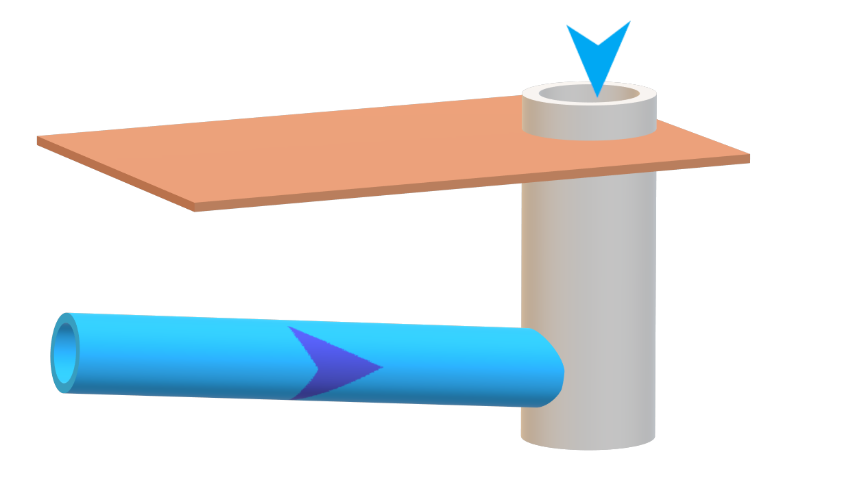
--Culvert Opening--
Description:
- Surface node that connects an open conduit to the surface geometry
Conditions:
- Single conduit connection entering or leaving the node
- Crown of connected conduit is above the terrain (or terrain elevation override value)
- Node must intersect a 1D or 2D surface element
Parameters:
- Boundary conditions are not allowed
- Drop inlets are not allowed
- Cannot have volume (i.e., Base Area = 0)
Boundary Conditions Accepted
- None
Common Use Cases:
- Used to model culvert ends
- Used to model location where pipe network daylights or outfalls to the surface geometry
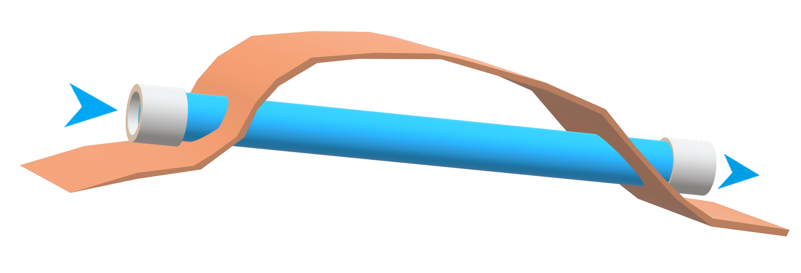
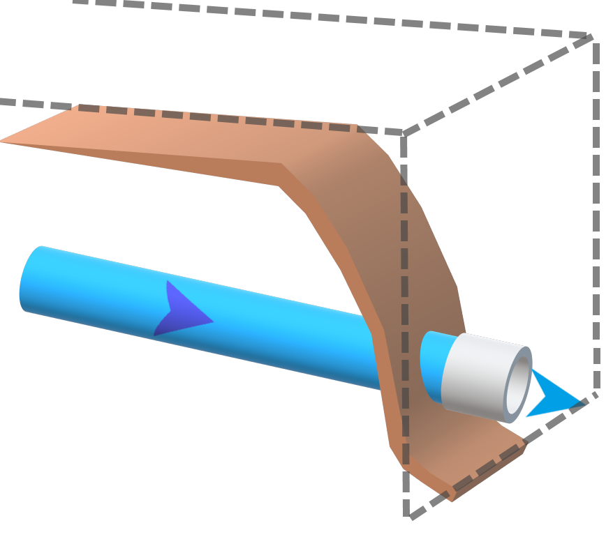
--External--
Description:
- Surface node at the downstream end allowing flow to leave the model domain
Conditions:
- Single conduit connection entering the node
- Crown of connected conduit is above the terrain (or terrain elevation override value)
- Must not intersect a 1D or 2D surface element
Parameters:
- Drop Inlets are not allowed
- Cannot have volume (i.e., Base Area = 0)
Boundary Condition Accepted
- Stage Hydrograph
- Normal Depth
Common Use Cases:
- Used to model outfalls from the pipe network leaving the model domain
- Used to model downstream stage boundary condition (such as tidal)
--Error--
Description:
- Node type cannot be determined because of missing incorrect information
Conditions:
- Missing conduit connections
- Missing required attribute information
Notes:
- The reasoning for the error designation will appear in the Node Status attribute Column or the Error Layer for the Geometry
Node Attributes
Provided that the drawn or imported Nodes and Conduits are connected and an associated terrain exists, the minimum required attributes for a valid Node geometry layer are Invert Elevation, System Name, Terran Elevation, and Base Area.
| Attribute | Automatically Populated, Required, or Optional | Description |
|---|---|---|
| Name | Required | The name or ID of the node. |
| System Name | Automatically Populated | The name or ID of the overall pipe network that the node belongs to. This is automatically populated based on the System Name of the connecting conduits. |
| Node Type | Automatically Populated | The type of node, and is used to determine how computations are handled at the node. This is automatically populated based on the number of conduit connections, the direction of conduit connections, the depth of the connected conduits relative to the terrain (or terrain override elevation) and whether a surface geometry exists at the node. Additional information about the node types can be found in the Node Types Section . |
| Node Status | Automatically Populated | An informational field that provides more detail about the junction type, indicates if a valid drop inlet exists on the node, and will provide error messages if attribute data is entered incorrectly of missing. |
| Conduit Connections (US:DS) | Automatically Populated | An informational field that shows the number upstream and downstream conduits connected to the node, separated by a colon. # Upstream connections : # Downstream connections |
| Invert Elevation | Required | The elevation of the bottom of the node. For nodes that represent a structure (such as a manhole) this is the invert elevation of the structure. For nodes that represent the end of a culvert, this is the invert elevation of the culvert. |
| Terrain Elevation | Automatically Populated | The elevation value of the associated terrain at the node location. |
| Terrain Elevation Override | Optional | A user provided elevation value used to override the Terrain Elevation value. This value can be used when the computed Node Type is incorrect due to the resolution or accuracy issues of the associated terrain at the node. This is an alternative to using Terrain Modifications to override the terrain. For example when the desired Node Type is Culvert Opening, but the Terrain Elevation is causing the Node Type to be Start or Closed, the Terrain Elevation Override can be set to a lower value to allow the node to behave as a culvert opening. |
| Depth | Automatically Populated | The depth of the node. This is an informational field that is automatically populated by subtracting the invert elevation from the Terrain Elevation (or terrain elevation override). |
| Base Area | Required | The area of the structure (in model length units squared). This field is typically used to represent the area of a manhole of junction box. If there is no structure (e.g., a Culvert Opening, or External Node) the base area should be set to 0. This field is used in the computation of volume - elevation curves for node cells. |
| Drop Inlet Elevation | Optional | The rim elevation of the node's Drop Inlet structure. This is the elevation at which surface water enters the node, or exits the node when surcharging. When the Drop Inlet Elevation is specified here, the remainder of the Drop Inlet attributes below are required. Drop Inlets can only be present at the following Node Types : Junction, Start, Closed. Drop Inlets must be connected to surface geometry, so the node must be located within a 1D or 2D geometry element to have a valid Drop Inlet |
Drop Inlet Weir Length | Optional | The length of the Drop Inlet structures edge spilling into the node. This value is used to calculate weir flow from surface elements into the drop inlet. Typically will be the circumference of the drop inlet or catch basin structure opening. |
| Drop Inlet Weir Coef | Optional | The weir coefficient used for weir flow calculations from the surface into the Drop Inlet. The default is 3 |
| Drop Inlet Orifice Area | Optional | The surface area of the drop inlet structure spilling into the node. This is used to calculate orifice flow from surface elements into the drop inlet. For example, for a circular stormwater inlet grate, this value would be the open area of the grate |
| Drop Inlet Orifice Coef | Optional | The orifice coefficient used for orifice flow calculations from the surface into the Drop Inlet. The default is 0.67. |
Conduits
Conduit Attributes
Provided that the drawn or imported Nodes and Conduits are connected and an associated terrain exists, valid Conduit geometry requires at a minimum, System Name, Modeling Approach, Mesh Cell Length, Rise/Span, Manning's n US/DS Offsets, and Entrance/Exit Losses.
| Attribute | Automatically Populated, Required, or Optional | Description |
|---|---|---|
| Name | Required | The name or ID of the conduit. |
| System Name | Required | The name or ID of the overall pipe network system that the conduit belongs to. Multiple pipe network systems are allowed in a single geometry and each system can be assigned specific Compute Options (computation interval, initial conditions, etc.). This is analogous to having multiple 2D Areas in an HEC-RAS geometry. A default name of 'Base' is provided for newly added conduits. |
| US Node | Required | The name of the upstream node connected to the conduit. |
| DS Node | Required | The name of the downstream node connected to the conduit. |
| Modeling Approach | Required | The modeling approach that will be used to perform calculations within the conduit. The two option include Hydraulic or Instantaneous. Hydraulic is the default method, which routes water using the 1D finite-volume hydraulics engine. The Instantaneous method transfers water instantaneously from the upstream to the downstream end of the conduit. This can be useful for reducing model complexity and run times on short lateral line conduits feeding main conduit lines. Note, conduits using the Instantaneous modeling approach can not be downstream of Hydraulically modeled conduits. |
| Length | Automatically Populated | The length of the conduit in model units. This is the length of the conduit polyline and will be used to compute hydraulic property tables for the conduit. |
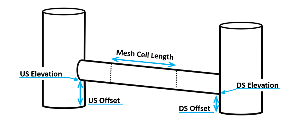
| Mesh Cell Length | Required | The length used to discretize the pipe into finite volume mesh cells. For example, a 120 foot pipe with a Mesh Cell Length of 10 will be discretized into 12 cells. Note, the final mesh cell length for a pipe can vary from the requested length based on the characteristics of the junction cells on either end. |
| Shape | Required | The cross-sectional shape of the conduit. HEC-RAS currently has the following shapes: Circular, Box (rectangular), Ellipse, Arc, Semi-Circle, Low Arch, High Arch, ConSpan Arch. More on shapes can be found in the Conduit Shapes section below. |
| Rise | Required | The maximum vertical dimension of the conduit cross section. In the case of circular pipes, this is equivalent to the pipe diameter. |
| Span | Required* | The maximum horizontal dimension of the conduit cross section. Span is used to define cross-sectional shapes beyond simple circular. However, In the beta release, Span should be set equal to Rise for circular sections. |
| Manning's n | Required | The Manning's n roughness value of the pipe. |
| US Offset | Required | The height of the conduit invert above the upstream node invert. This value is added to the connected upstream node's invert to get the US Elevation value for the conduit. Only values >0 are accepted. Most often this value is 0 meaning the conduit leaves the upstream manhole at the bottom elevation of the manhole. An US Offset of 1 foot means that the conduit leaves the junction 1 foot above the elevation of the bottom of the manhole. |
| DS Offset | Required | The height of the conduit invert above the DS node invert. This value is added to the connected upstream node's invert to get the DS Elevation value for the conduit. Only values >0 are accepted. Most often this value is 0 meaning the conduit enters the downstream manhole at the bottom elevation of the manhole. An DS Offset of 1 foot means that the conduit enters the junction 1 foot above the elevation of the bottom of the junction. |
| US Elevation | Automatically Populated | The upstream invert elevation of the conduit. This value is computed by adding the US Offset to the upstream node Invert Elevation. |
| DS Elevation | Automatically Populated | The downstream invert elevation of the conduit. This value is computed by adding the DS Offset to the downstream node Invert Elevation. |
| Slope | Automatically Populated | The slope of the conduit given the upstream elevation, downstream elevation and length. |
| US Entrance Loss Coefficient | Required | The entrance loss coefficient applied to water flowing into the upstream end of the conduit. This, and the following loss coefficients represent minor losses at the connection of pipes to junction boxes. |
| US Backflow Loss Coefficient | Required | The exit loss coefficient applied to water backflowing out of the upstream end of the conduit. |
| DS Exit Loss Coefficient | Required | The exit loss coefficient applied to water flowing out of the downstream end of the conduit. |
| DS Backflow Loss Coefficient | Required | The entrance loss coefficient applied to water backflowing into the downstream end of the conduit. |
| DS Flap Gate | Required | A checkbox to allow for the inclusion of a flap gate at the downstream end of the conduit. If a flap gate is applied, water will not be allowed to backflow into the conduit from the downstream end. |
| Major Group | Optional | Conduit group name used to group sections of the pipe network for easier profile plotting and other results viewing. |
| Minor Group | Optional | Conduit subgroup name used to group sections of the pipe network for easier profile plotting and other results viewing. |
Conduit Shapes:
Several different conduit cross-sectional shapes are available to use in pipe networks. These shapes are analogous to the ones used in the HEC-RAS culvert editor for inline, lateral, and SA/2D structures. These shapes include: circular; box (rectangular); arch; low profile arch; high profile arch; ellipse (horizontal and vertical); semi-circular, and Con/Span culverts (see figure below).
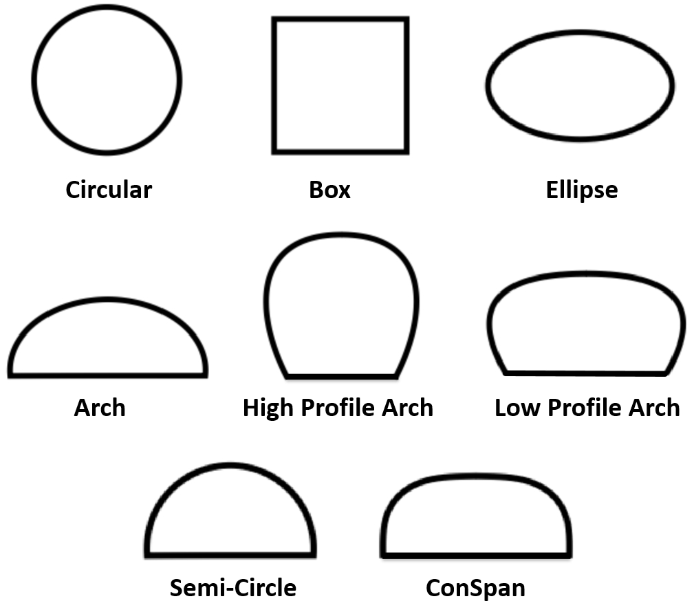
As described in the conduits attribute section the size of each shape is determined by a Rise and Span parameter which represent the maximum height and width inside the conduit. Note, for circular and semi-circular conduits, the rise and span should bet set to the same value.