HEC-RAS has long had the capability to model pressurized pipe flow utilizing the Preissmann slot approach with lidded cross-sections; however, the ability to perform integrated urban stormwater modeling with networks of subsurface conduits was lacking. In version HEC-RAS 6.6, functionality for creating pipe networks and integrating them with 1D and 2D surface water geometry elements was released in Beta form. The addition of stormwater pipe networks expands the applicability of HEC-RAS in urban areas, allowing users to analyze the adequacy of stormwater systems and better characterize pluvial flooding and interior drainage.
Pipe Networks are released as a beta feature in HEC-RAS version 6.6. The beta tag intended to indicate that we will be gathering feedback from the field about the implementation, and we expect further changes and improvements to be made before an official release.
Methodology and Capabilities
The computational procedure for pipe networks in HEC-RAS is unlike that of other popular stormwater modeling software in that the pipe flow computations are performed with a 1D finite volume solver. Similar to the 2D hydraulic computations in HEC-RAS, a mesh is created from the pipe network geometry attributes and sub-grid property tables are computed for the pipe cells and faces. The pipe network mesh is modeled independently of the surface model and interacts with the surface where connections are made between the pipe network and the 1D or 2D surface geometry. This computational approach for pipe networks in HEC-RAS allows:
- Capability for open-channel/pressure flow transitions within a pipe
- Capability for supercritical flow and hydraulic jumps
- Capability for plunging flows
- Capability for wetting and drying of the pipe network
- Stability at low flow flows and steep slopes
- Variable computation cell size throughout the system
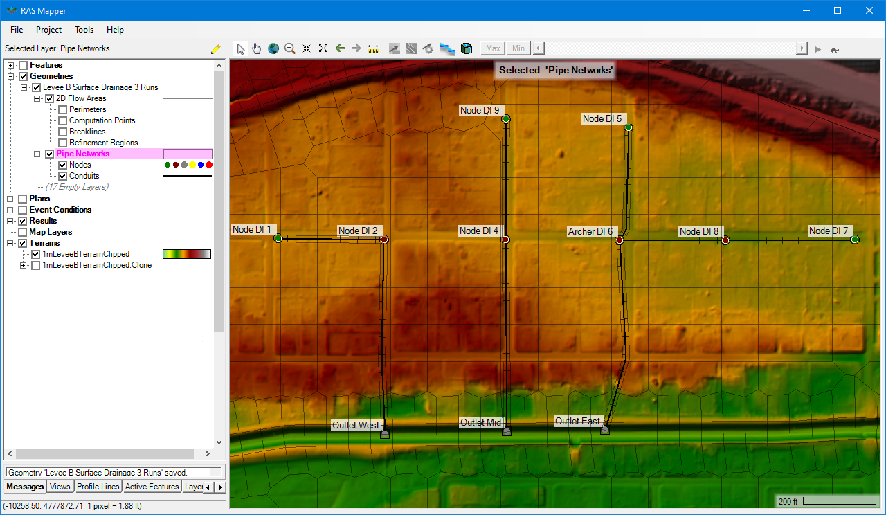
The figure below shows an example of a small pipe network integrated with a 2D area. In this example when rainfall is applied to the 2D area, drop inlets at the node locations control flow from the 2D area into the pipe network, and the pipe network outfalls back into the 2D channel on the south end.
Geometry
Pipe network geometries are defined by nodes (represented by a points layer) and conduits (represented by a polyline layer), and their associated attributes. Pipe network geometries can be created by drawing nodes, drawing connecting conduits and defining the attributes of nodes and conduits in their respective tables, all in HEC-RAS Mapper.
Creating pipe network geometry can also be done via a shapefile importer that allows users to import georeferenced features and map the corresponding attributes (inverts, conduit shape, size, roughness, etc.) to the appropriate HEC-RAS pipe network fields. This shapefile importer affords the flexibility to import geometry information from various sources such as utility maintenance files, design files, or other pipe modeling software. Finally, an EPA-SWMM input file (*.inp) importer is available to assist modelers in converting existing SWMM elements into HEC-RAS pipe networks.
Boundary Conditions
Flow into the pipe network occurs at the node locations, which can receive inflows from 1D and 2D surface model elements and receive inflow hydrographs computed externally. Node connections to surface elements are characterized as either drop inlets that can be used to model catch basins and curb inlets, or as conduits that daylight to model free outfalls and culverts. Additionally, when conduits become pressurized, flow can surcharge from nodes into the surface geometry elements. External boundary conditions can also be applied at nodes, allowing modelers to add inflow hydrographs or set downstream stage and normal depth conditions.