Download PDF
Download page Creating layouts.
Creating layouts
Data
This tutorial follows the “creating a study area” tutorial. If that tutorial was completed successfully, then no additional data are needed here. If you are starting anew, please download a copy of “EFMSim Spatial Setup.zip” and extract contents to your computer. Images in this tutorial use files extracted to C:\Temp\EFMSim\. Data layers are for a reach of the Truckee River at Lockwood, Nevada.

Objective
This tutorial shows how to create layouts in EFMSim by 1) manually creating elements via actions such as drawing, merging, and filling, 2) importing elements from existing layouts and data layers, and 3) importing layouts from other projects.
Note: In EFMSim, there is one study area per project. Layouts are collections of elements that wholly fill the study area. Elements are the finest spatial resolution considered during simulations. There are typically many elements per layout. There can be multiple layouts per project.
Creating layouts – Drawing, merging, and filling
1. Start HEC-EFMSim and open the EFMSim project.
If you are continuing from the study area tutorial, please consider using the File - Save Project As... menu to save your project with a new name such as "Layouts". Also consider updating your study area to look like the images below, if necessary.
If you would like to use the project provided for this tutorial, please use the File - Open menu to open a project called “Tutorials_-_Layouts.prj”, which is located in the \Tutorials\Tutorials_-_Layouts\ folder.
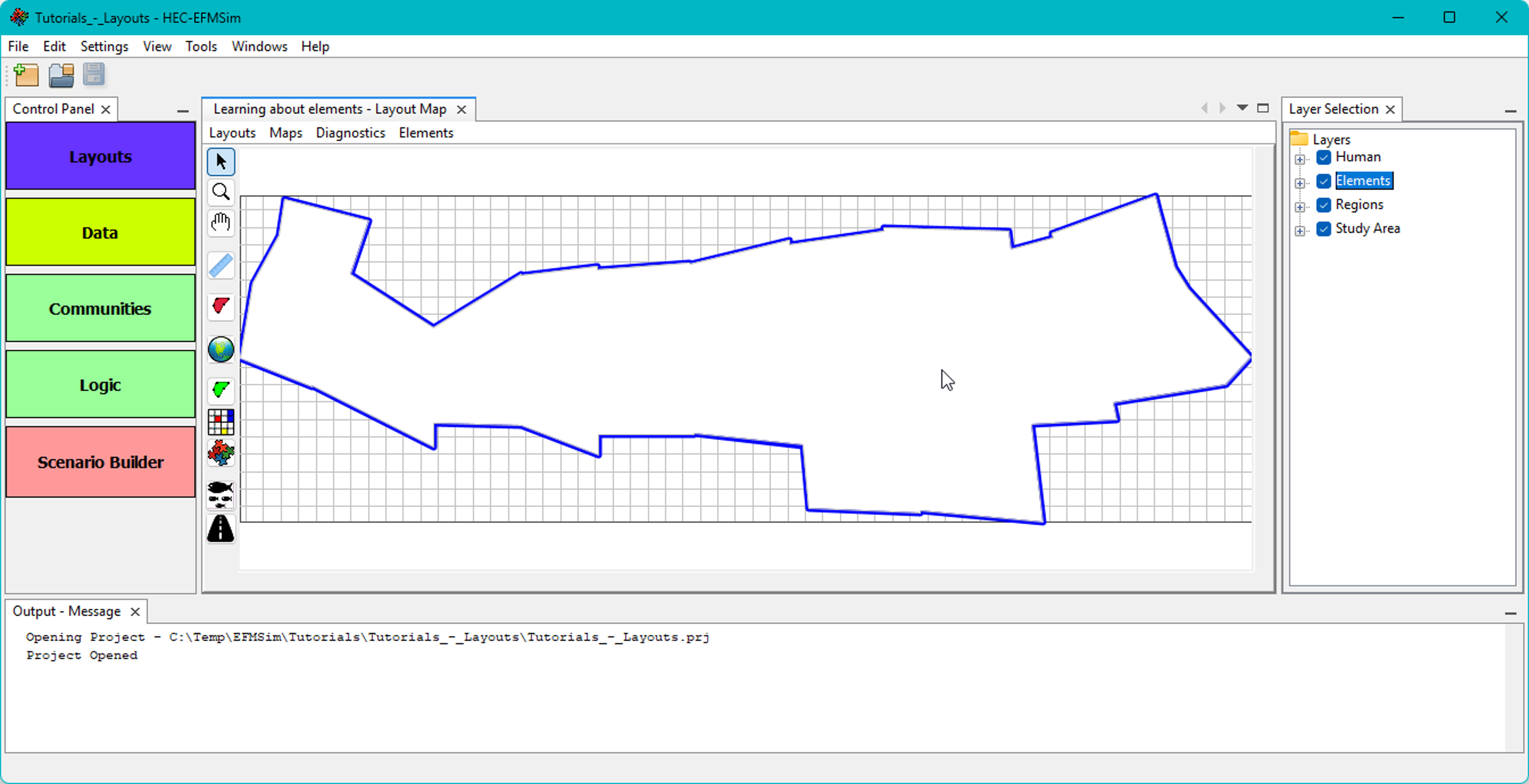
2. If a Layout Maps interface is not open, click the purple “Layouts” button in the Control Panel or select the Windows | Layouts | All menu option to open a Layout Map and an associated Layer Selection window.


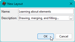
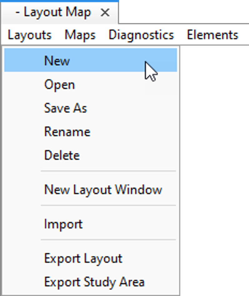
3. Select the Layout Maps | Layouts | New menu option. Enter layout name and description (optional) and click the OK button.

4. The new layout is created and populated with one element that wholly fills the study area.
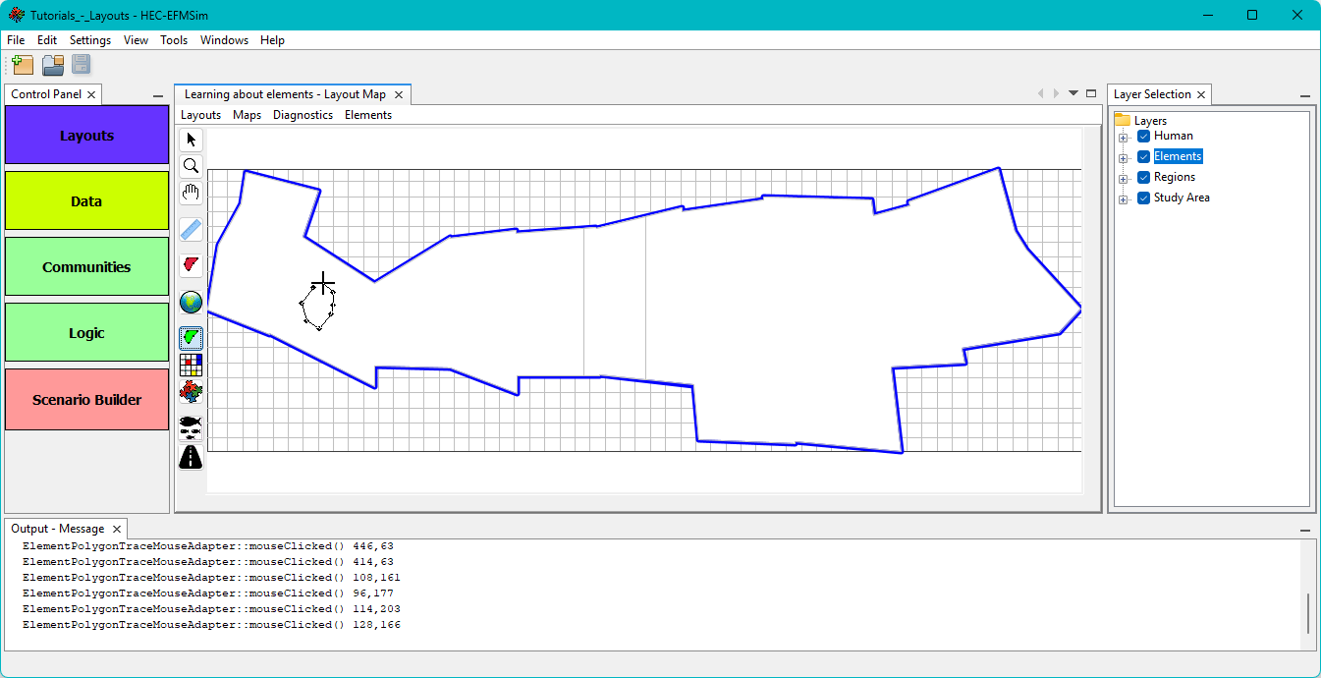
5. Click the Element Draw button to activate a polygon drawing tool. The cursor will change to a “+”. Press and hold the control key and use left mouse clicks to set vertices. Release control key and enter final left click to close polygon. Please draw a few elements. Note, element polygons drawn partially outside of the study area will be cropped to the study area boundary.


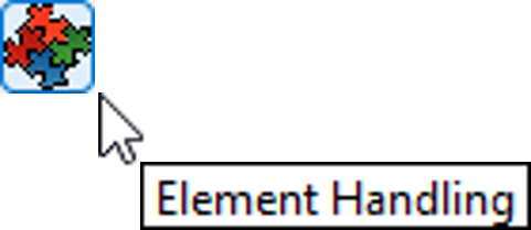
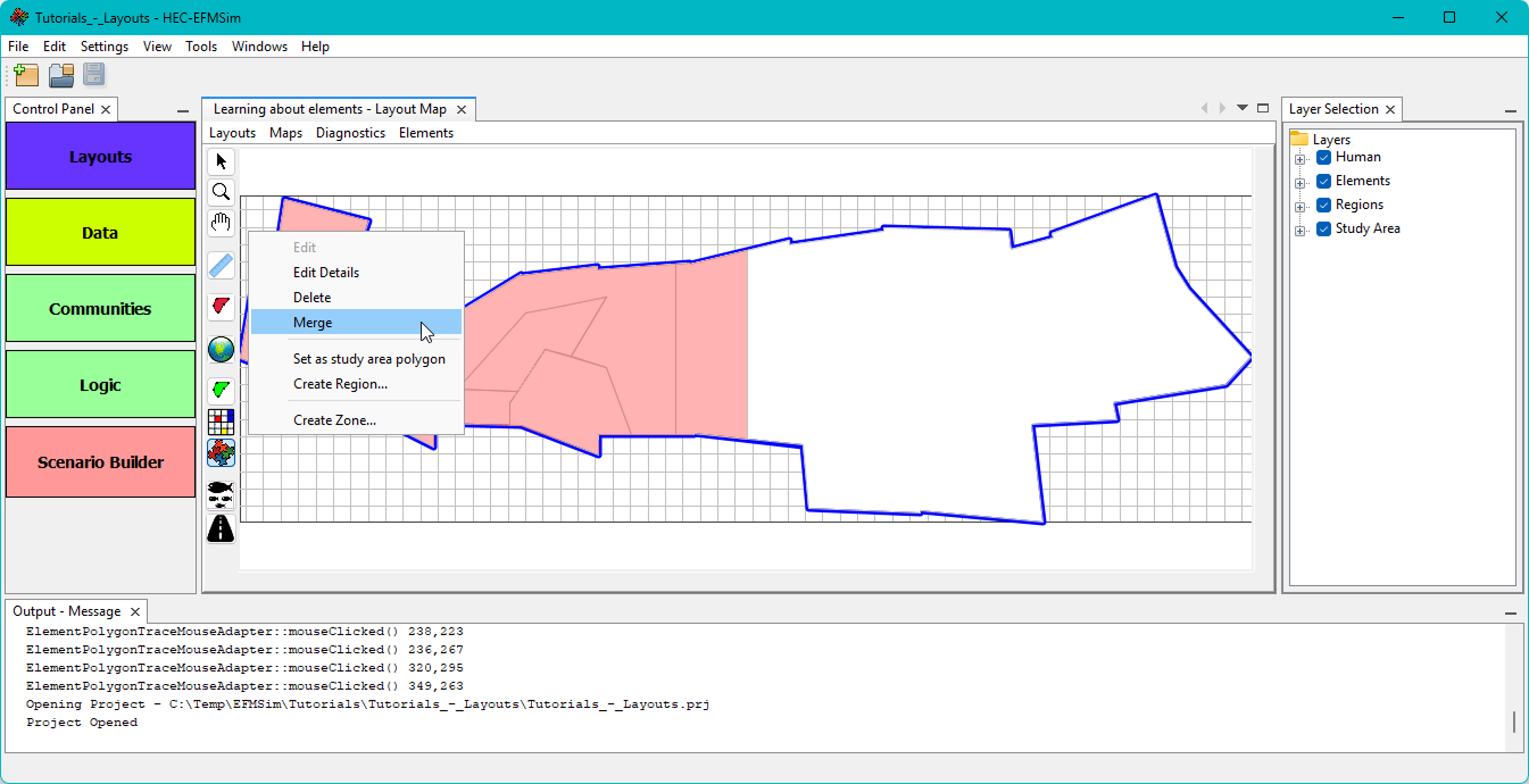
6. Click the Elements Handling button. This tool has several functions, including selection and merging or deleting of elements. Elements can be frame selected by clicking and holding the left mouse button and dragging the frame to the desired extent. Elements can also be selected by pressing and holding the shift key and then clicking and holding the left mouse button to lasso desired elements. Pressing and holding the control key enables left mouse clicks to select and deselect individual elements.
Select two or more of the drawn elements and use the right click menu to Merge the selected elements.

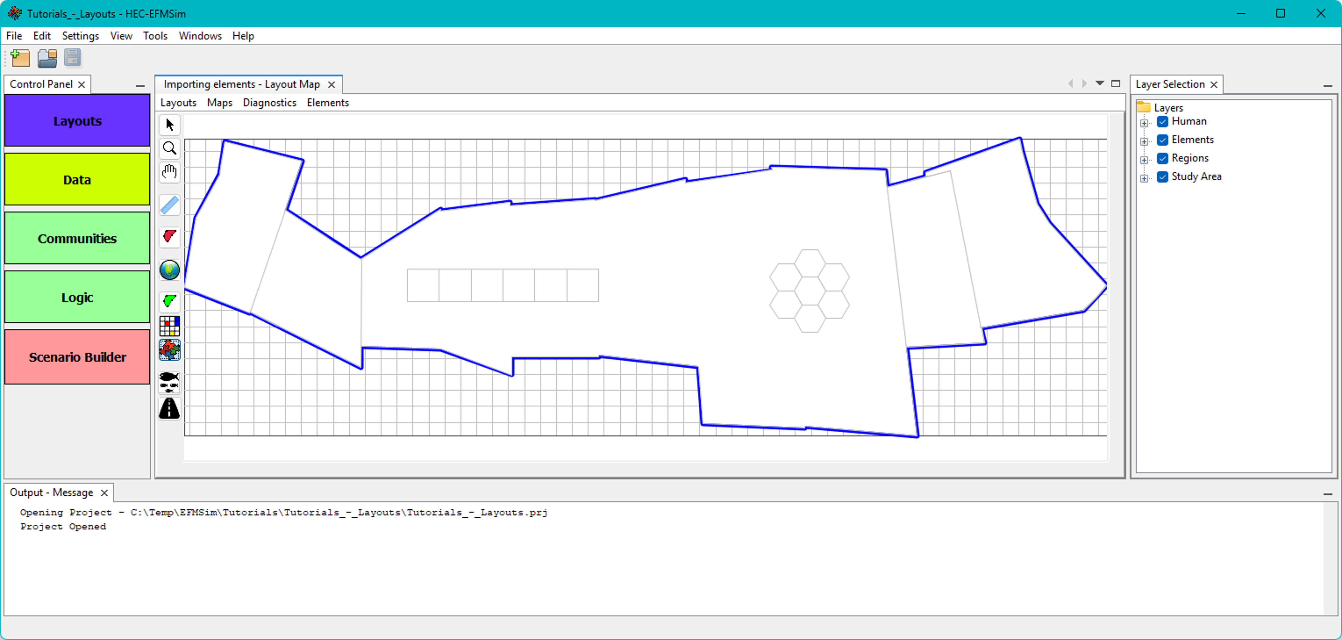
7. Click the Element Fill button and select an element. Right click on the selected element and select the Fill menu option. Try the Fill with grid option.

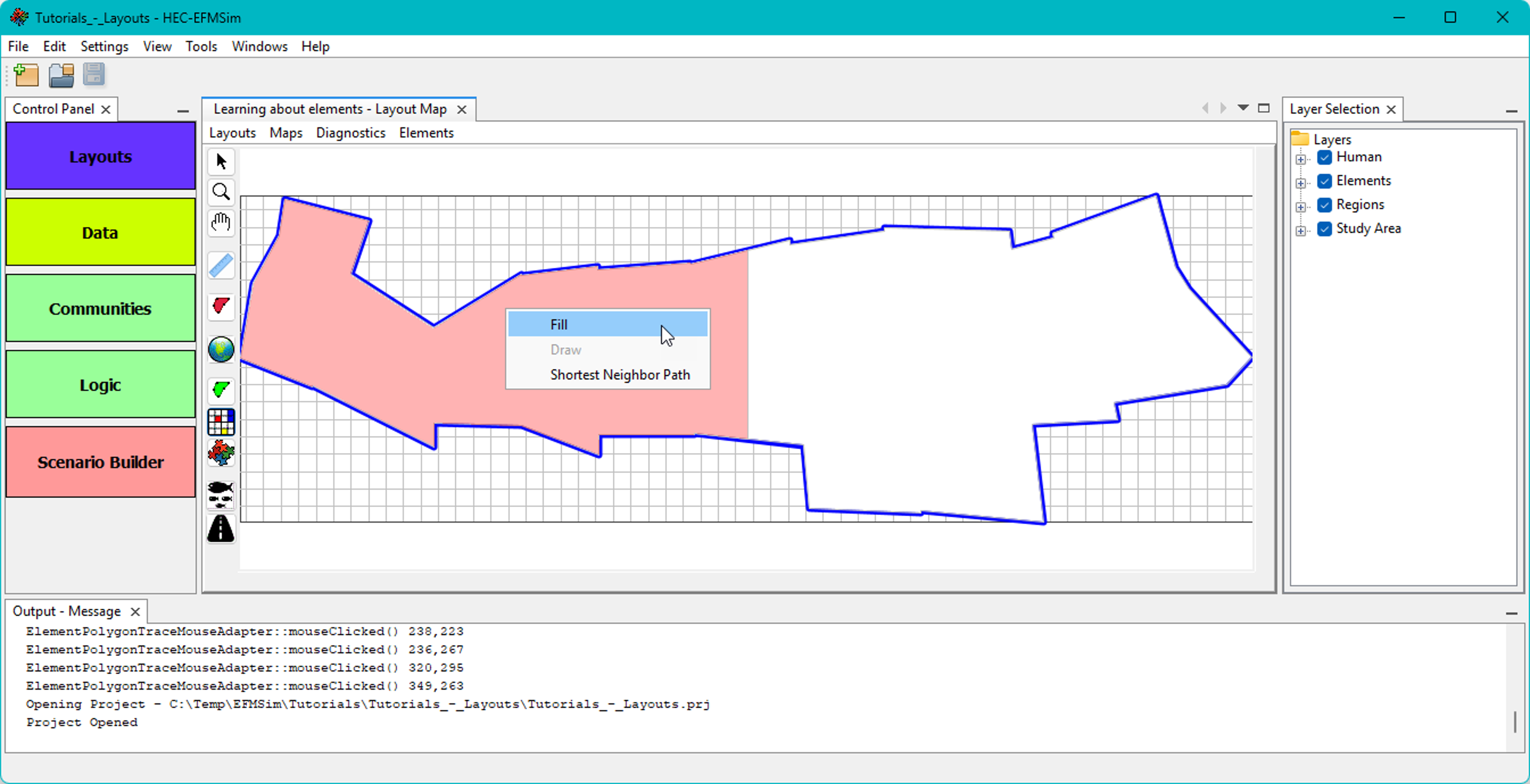

8. Select a different element. Right click on the selected element and select the Fill menu option. Try the Fill with hexagons option.


Creating layouts – Importing elements from existing layouts and data layers
1. Select the Layout Maps | Layouts | New menu option. Enter layout name and description (optional) and click the OK button.

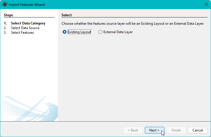
2. Select the Layout Maps | Elements | Import Elements menu option. The Import Features Wizard will open. Select the Existing Layout option and click the Next button.

3. Select the “Learning about elements” layout that was created previously as part of this tutorial and click the Next button. The Import Features Wizard works with other layouts that are part of the active project.

4. The wizard interface will show the selected layout. Elements can be frame selected by clicking and holding the left mouse button and dragging the frame to the desired extent. Elements can also be selected by pressing and holding the shift key and then clicking and holding the left mouse button to lasso desired elements. Pressing and holding the control key enables left mouse clicks to select and deselect individual elements. Select a few elements and click the Import Elements button.

5. When the import is complete, click the Finish button to close the wizard.

6. Select the Layout Maps | Elements | Import Elements menu option. The Import Features Wizard will open. Select the Existing Layout option and click the Next button.


7. Browse to the \maps_truckee\ directory, select “Study_area_sections.shp”, and click the Next button.

8. Select a few features and click the Run Import button.

9. When the import is complete, click the Finish button to close the wizard.

Creating layouts – Importing layouts from other projects
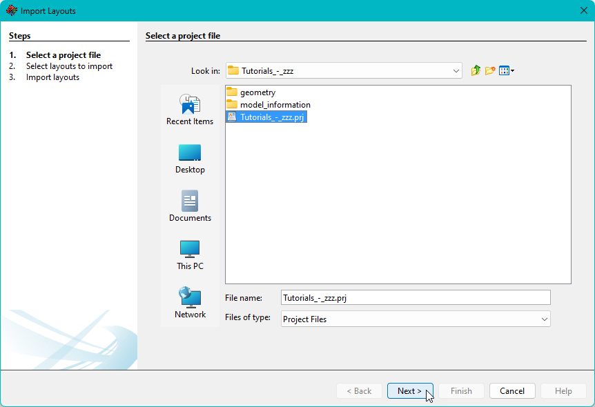
1. Layouts can also be imported from other projects. Select the Layout Maps | Layouts | Import menu option.

2. Browse to and select the “Tutorials_-_zzz.prj” project and click the Next button. “Tutorials – zzz.prj” is an EFMSim project developed for instructional purposes (i.e., here used as a source project for layouts).
3. The Import Layouts Wizard will show layout lists for the current project and the selected project. Select one or more of the layouts to import. Click the “>>” button to move a copy of the selected layout(s) to the current project and then click the Next button.

4. Click the Import button to import.

5. When import is complete, click the Finish button to close the wizard. The imported layout will be added to the current project and can be opened via the Layout Maps | Layouts | Open menu option.

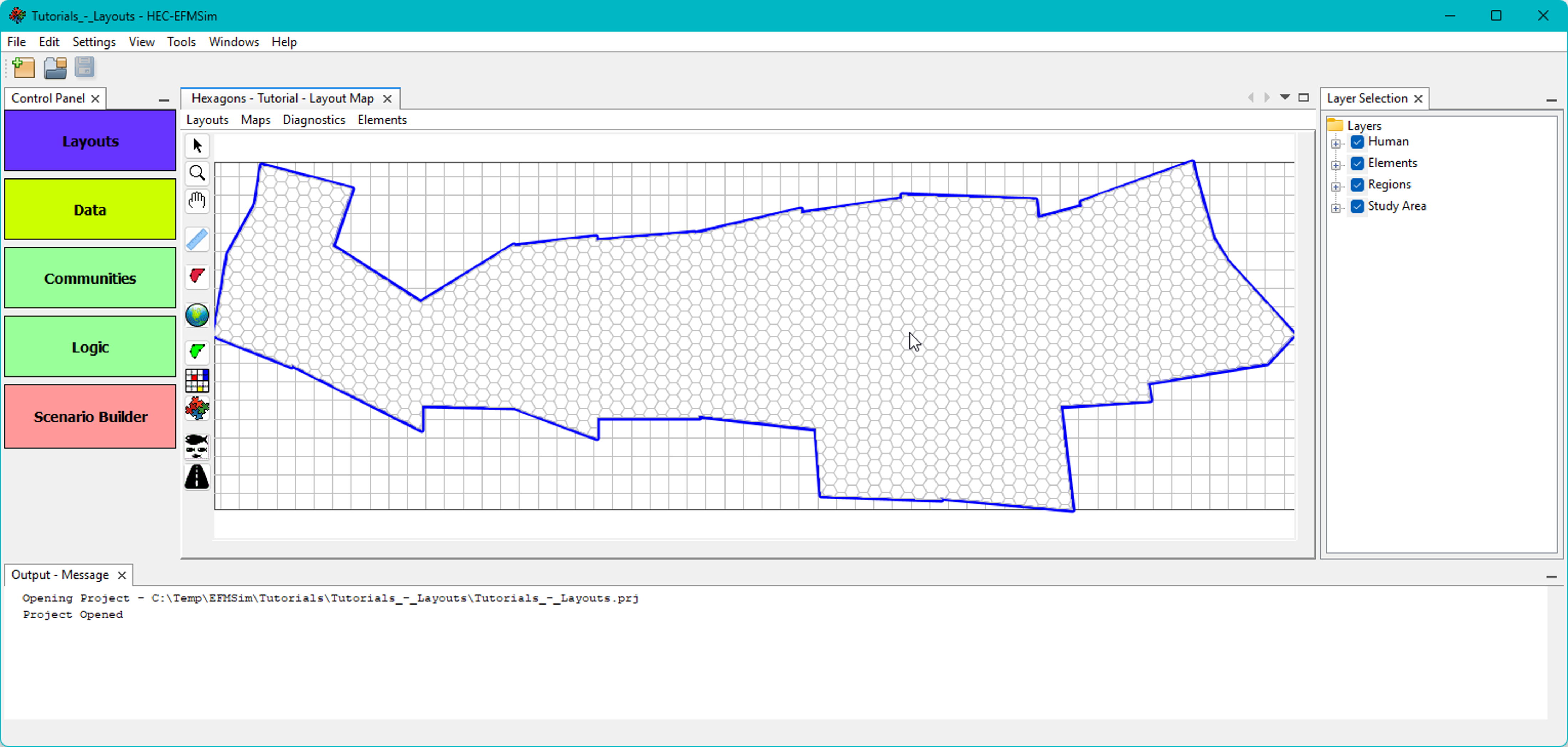
It is important to note that when a layout is imported, any map layers associated with that layout are also imported. Please see the map layers tutorial more information.