Download PDF
Download page Working with map layers.
Working with map layers
Data
This tutorial follows the “creating layouts” tutorial. If that tutorial was completed successfully, then no additional data are needed here. If you are starting anew, please download a copy of “EFMSim Spatial Setup.zip” and extract contents to your computer. Images in this tutorial use files extracted to C:\Temp\EFMSim\. Data layers are for a reach of the Truckee River at Lockwood, Nevada.

Objective
This tutorial shows how to work with map layers in EFMSim by 1) using aerial imagery, 2) importing map layers and base maps, and 3) managing symbology.
Working with map layers – Using aerial imagery
1. Start HEC-EFMSim and open the EFMSim project.
If you are continuing from the layouts tutorial, please consider using the File - Save Project As... menu to save your project with a new name such as "Map Layers".
If you would like to use the project provided for this tutorial, please use the File - Open menu to open a project called “Tutorials_-_Map_Layers.prj”, which is located in the \Tutorials\Tutorials_-_Map_Layers\ folder.
2. If a Layout Maps interface is not open, click the purple “Layouts” button in the Control Panel or select the Windows | Layouts | All menu option to open a Layout Map and an associated Layer Selection window.

3. If it’s not already open, use the Layout Map | Layouts | Open menu option to open the Hexagons – Tutorial layout.

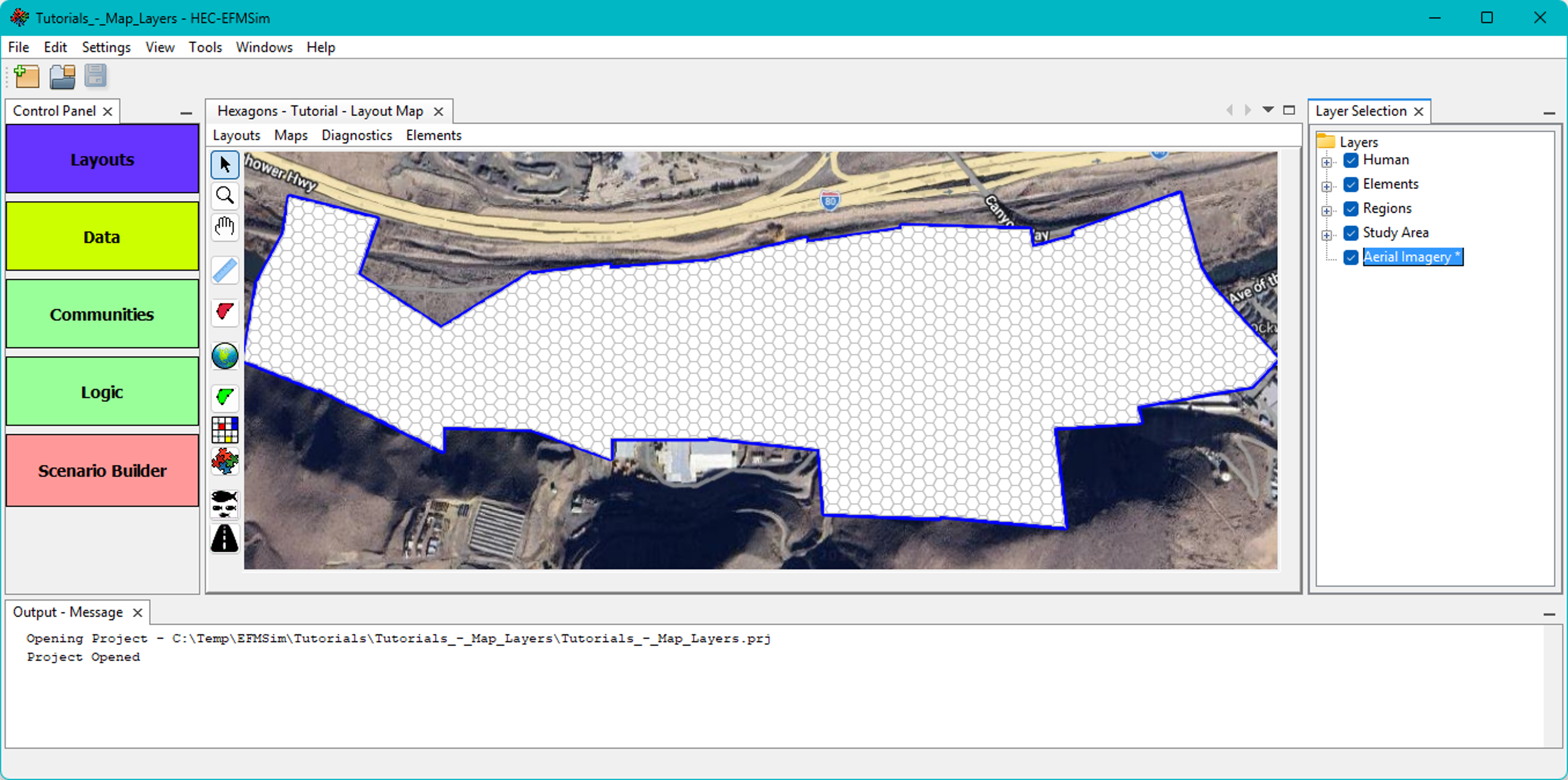
4. Select the Settings | Aerial Imagery | Google Street Map menu option.

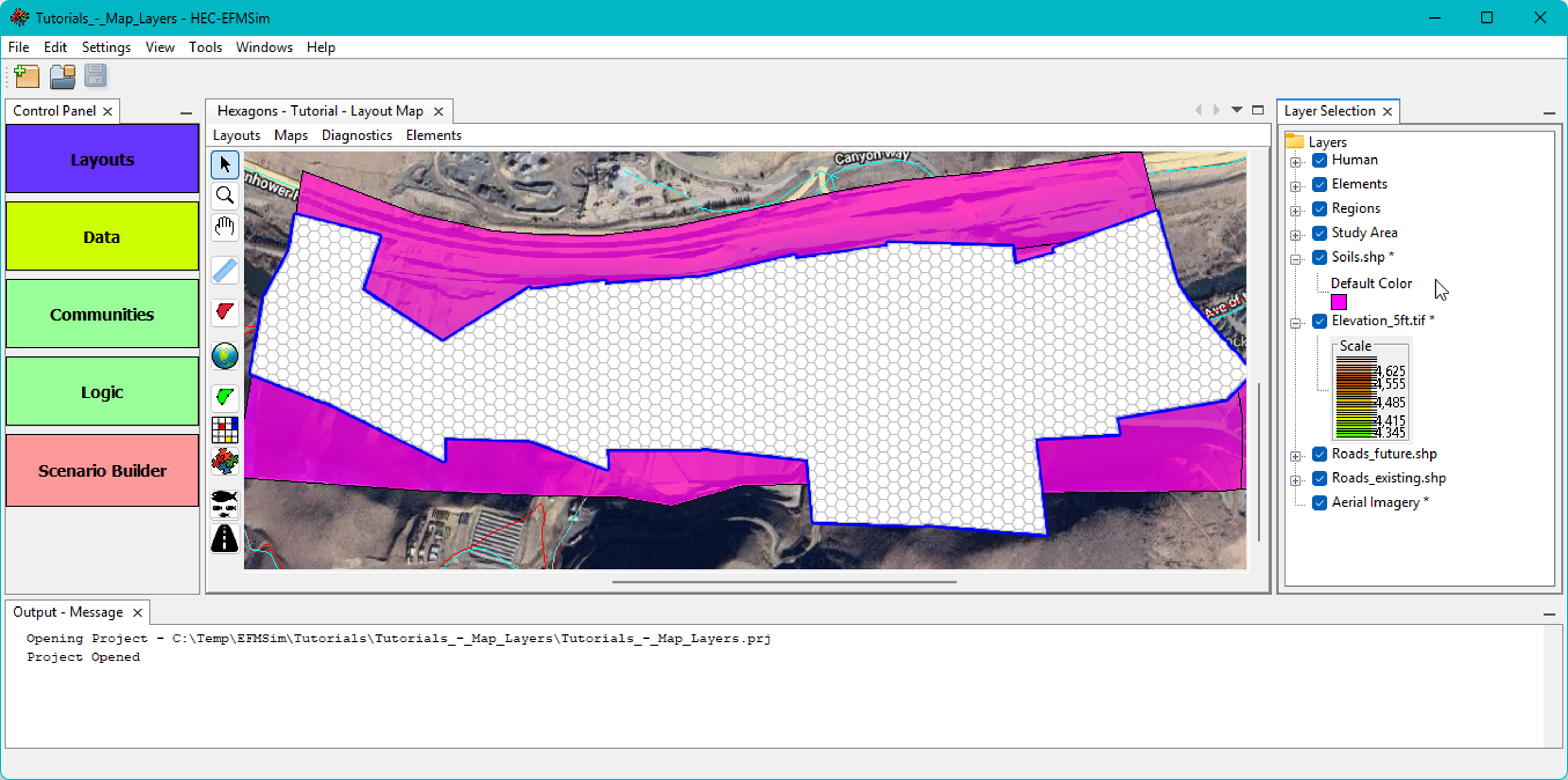
5. A layer called “Aerial Imagery” will be added to the Layer Selection tree. It is marked with an asterisk to acknowledge that it will be included for all map windows. Right click on that layer and select the Move to Bottom menu option.
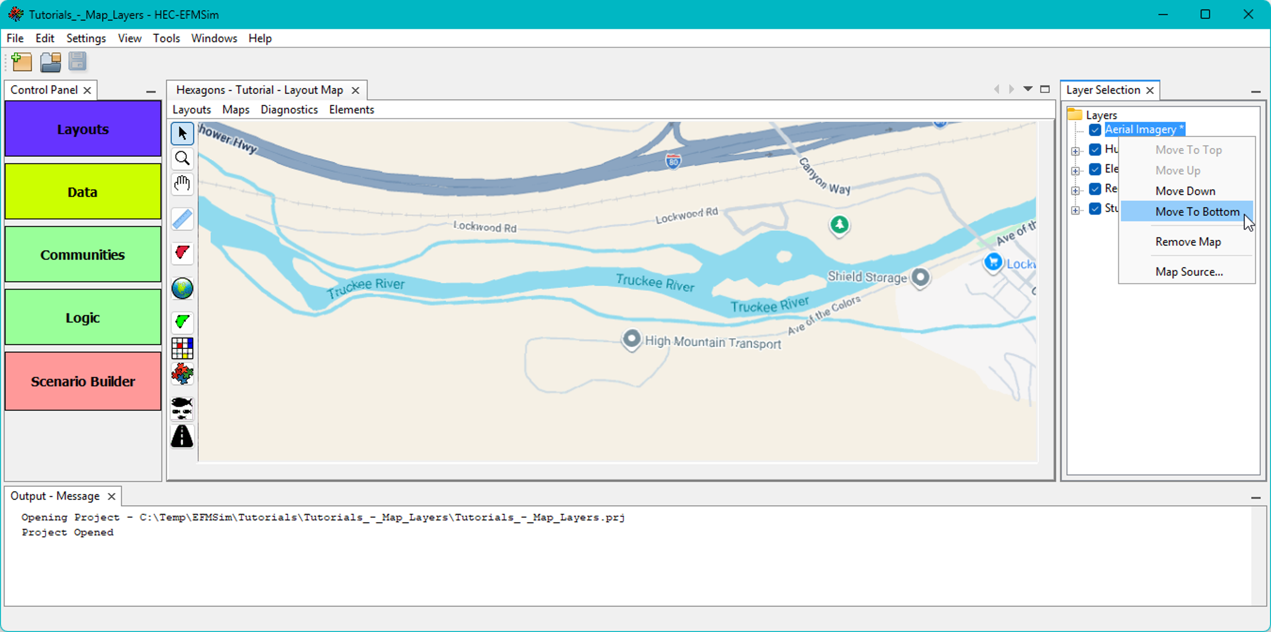
6. In EFMSim, aerial imagery is obtained from online map sources. The source can be changed via the Settings | Aerial Imagery menu or by right clicking on “Aerial Imagery” in the Layer Selection list and clicking the Map Source… menu option.

Please note that aerial imagery is not compatible and cannot be used with the generic X-Y coordinate system.
Working with map layers – Importing map layers and base maps
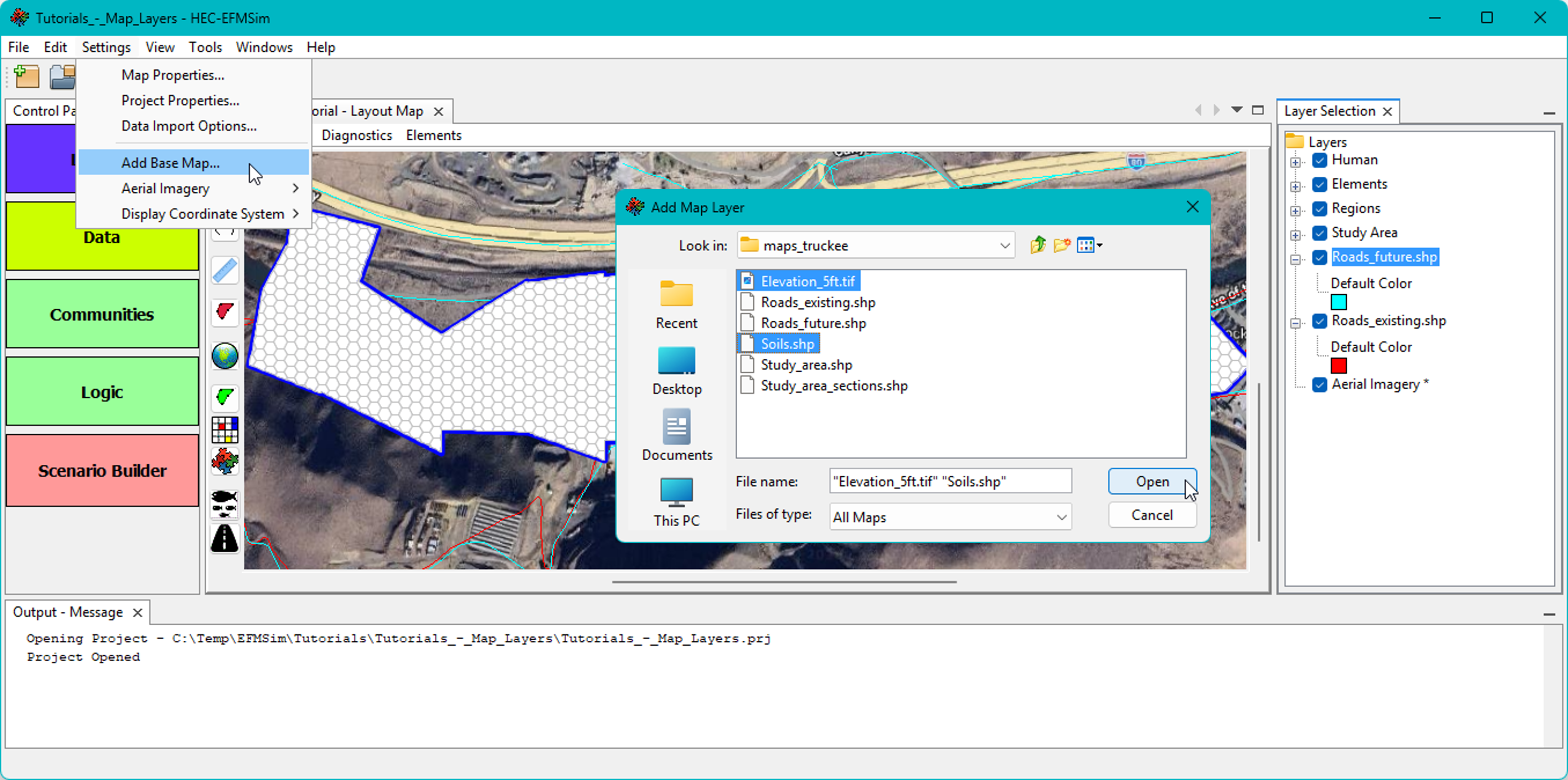
1. Map layers and base maps are used in EFMSim for visualization purposes only (i.e., not used in computations). Base maps are displayed for all layouts. Map layers are associated with and displayed for individual layouts. If a map layer is desired for multiple layouts, it must be imported separately for each of the relevant layouts. Use the Layout Map | Maps | Add Map Layer menu option to add a map layer(s).

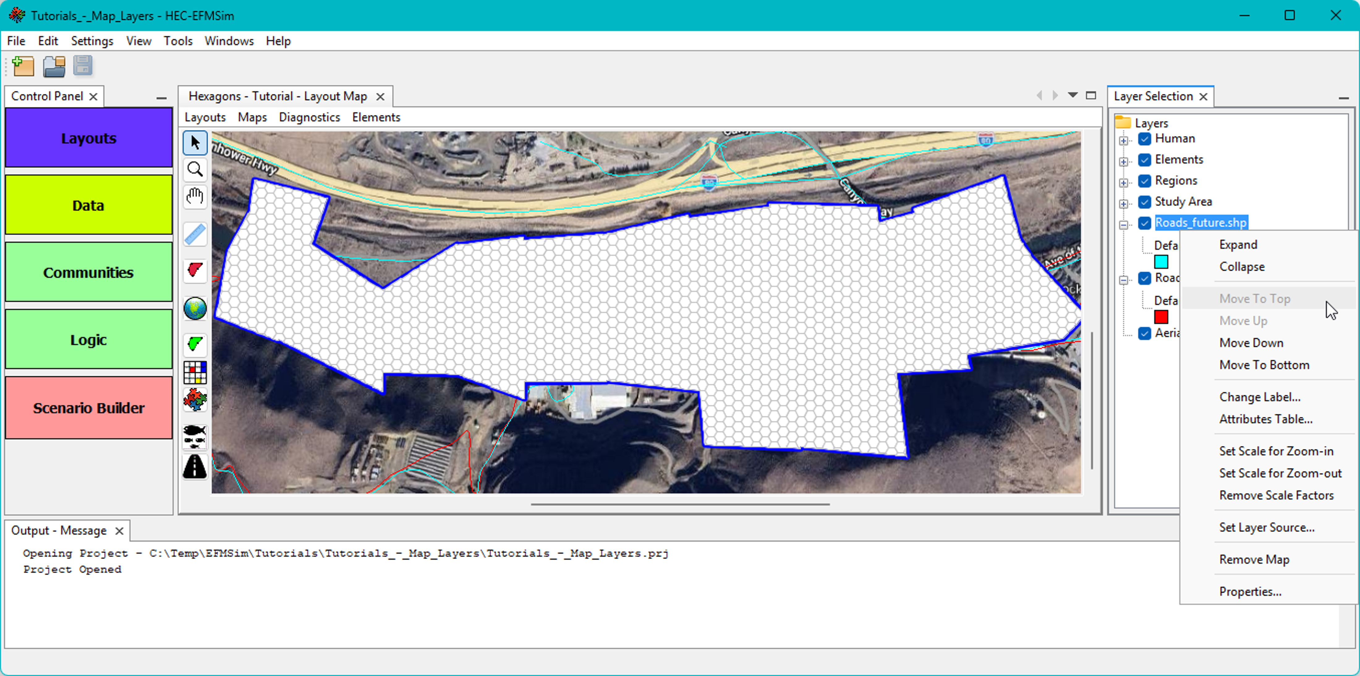
2. Map layers are added below the model-oriented features (i.e., Human, Elements, Regions, and Study Area). Map layers can be reordered for visualization purposes but cannot be moved above the model-oriented features in the Layer Selection list.
3. Use the Settings | Add Base Map… menu option to add a base map(s).
4. Base maps (and Aerial Imagery) are marked with an asterisk to acknowledge that those layers will be included for all map windows.
Please note that symbology for map layers is set and managed per layout. Symbology for base maps is set and managed per project (across all map windows) though base maps can be turned off in the Layer Selection list when not needed for visualizations.
Working with map layers – Managing symbology
1. Symbology for basemaps and map layers, as well as model-oriented features such as study area, elements, roads, and hatchery zones, is managed through the Layer Selection window. Symbology for polygons consists of line and fill styles. Symbology for polylines consists of line styles.
Right click on the Elements feature and select the Properties menu option to open an interface that allows update of symbology. Turn the Display Fill option off and select a Border color of your choice (this is an example of polygon symbology).

2. If you added one or both of the Roads layers, move those layers to the top of the map group and right click to access Properties… Choose your preferred Color and Weight and click OK (this is an example of polyline symbology).

3. Continue to adjust layer order, visibility, and properties until you are content with the symbology of model-oriented features, map layers, base maps, and aerial imagery.

Please note that layers added for visualization purposes can also be imported for use in simulations as datasets. Please see the EFMSim user’s manual for more information about data interfaces, import, and use.