In GeoEFM, the Splicing toolset assists with creation of habitat mosaics that are comprised of pieces from multiple layers. For example, Splicing could be used to create a mosaic that includes habitat in a tributary stream and its receiving river. In EFM, the stream and river would be assessed separately for the same habitat relationship because each has a different flow regime. Statistical results would be simulated with a hydraulics model to generate maps for the stream reach and for the river reach. Splicing tools in GeoEFM would assist with merging the two layers spatially to create a single map for that habitat type. The basic process for Splicing is to make a Splicing Configuration and then apply it to a set of layers. Though not shown in the images below, splicing can be done for overlapping and discontiguous areas.
GeoEFM executes splices per the following user specifications: Configuration, Snap Raster, and Overlap Method. Configurations for the Hydraulics Model Method and Polygons Method are detailed later in this guidance. The snap raster deals with offsets and cell size differences amongst the splice layers. Four options are provided for handling areas of overlap: proceed with maximum value, proceed with minimum value, first to splice, and last to splice (Figure 29).

Figure 29. A splice is based on a configuration, a snap raster, and an overlap option. The resulting mosaic reflects all of these user-selections.
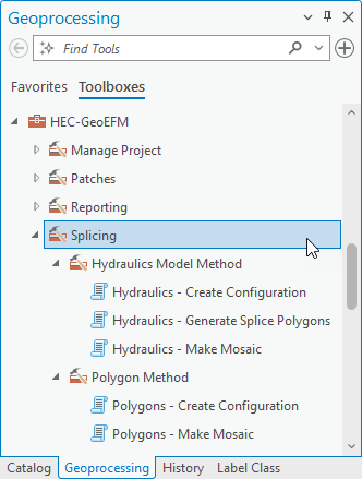
The Splicing toolset has two methods and five tools (Figure 30). The first method is the Splicing - Hydraulics Model Method and has three tools. The second method is the Splicing - Polygon Method and has two tools. Tools can be started via a double-left-click or via the right-click Open menu option.

Figure 30. The Splicing toolset has two methods and five tools.