Download PDF
Download page Stormwater Pipes in HEC-RAS.
Stormwater Pipes in HEC-RAS
By: Eric Tichansky, P.E., C.F.M.
Introduction
The Hydrologic Engineering Center's (CEIWR-HEC) River Analysis System (HEC-RAS) team is working diligently to include closed conduit modeling capabilities for stormwater applications in HEC-RAS version 6.6. This exciting new feature set will allow HEC-RAS users to create a stormwater pipe network and integrate the network with one-dimensional (1D) and two-dimensional (2D) surface elements. The addition of stormwater pipe networks will expand the applicability of HEC-RAS in urban areas, allowing users to analyze the adequacy of stormwater systems and better characterize pluvial flood risk. This effort was initially funded by the USACE Chicago District to support modeling of the Chicago Tunnel and Reservoir Plan (TARP), a deep underground tunnel and reservoir network used to reduce urban flooding and minimize combined sewer overflows. However, the effort has widened in scope to include features for modeling more typical stormwater systems, such as drop inlets and culvert type surface connections, pumps, flap gates, and more. Figure 1 shows the results of a pipe network simulation for a typical stormwater system in the city of Davis, California. In this example, rainfall is applied to a 2D area, drop inlets control flow from the 2D area to the pipe network, and a pump and free outfall boundary condition allow flow to leave the system.
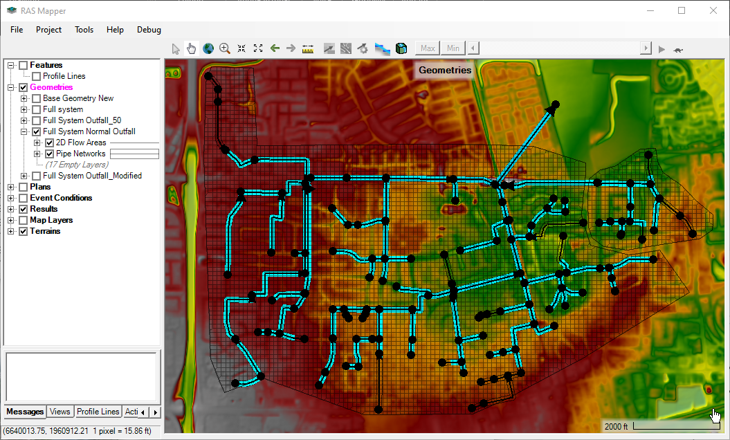
Figure 1. Pipe network simulation results in HEC-RAS Mapper.
HEC-RAS Methodology for Pipe Networks
The new pipe network implementation employs a 1D semi-implicit finite volume solver. This solver was developed by simplifying the existing 2D shallow water solver to 1D, then extending the solver to handle pressurized flows following the methods described in Casulli and Stelling (2013). A computational mesh is generated from the pipe network geometry attributes for conduits, including a specified mesh cell size, and the attributes for connecting nodes. Figure 2 show examples of this pipe network computational mesh in plan view (on the left) and profile view (on the right). From the mesh, sub-grid property tables are computed for cells and faces similar to the 2D solver; however, the property tables for pipe networks must be decomposed into positive and negative tables to account for the transition to pressure flow. The merits of taking this computational approach for pipe networks in HEC-RAS are:
- Capability for open-channel/pressure flow transitions within a pipe
- Capability for supercritical flow and hydraulic jumps
- Capability of plunging flows (shown on the right, below)
- Stability through wetting and drying of the pipe network
- Stability at low flow flows and steep slopes
- Variable computation cell size throughout the system
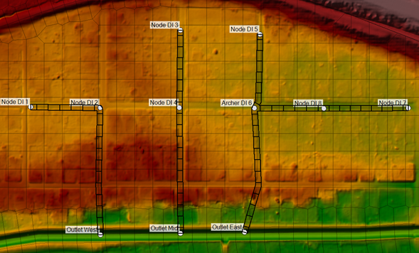
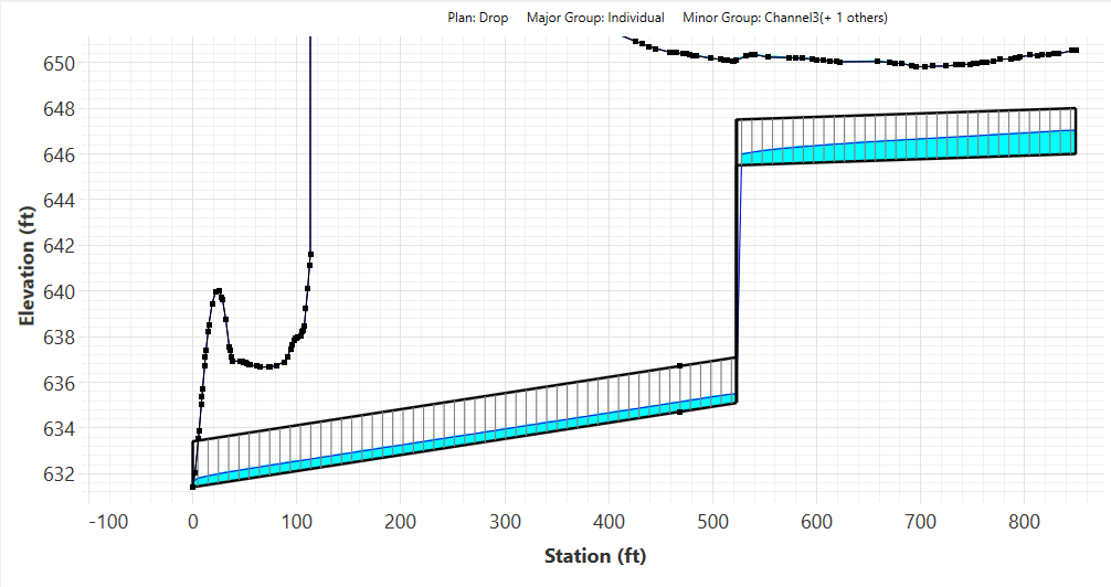
Figure 2. Example of a pipe network mesh in plan view, scaled for viewing (left-side); and an example in profile view showing plunging flow (right-side).
Creating Pipe Network Geometries
Pipe network geometries are defined by nodes (represented by a points layer) and conduits (represented by a polyline layer), and their associated attributes. Pipe network geometries can be created by simply drawing nodes and conduits in RAS Mapper, or importing existing georeferenced data describing the system. A shapefile importer allows users to import features and map source shapefile fields (inverts, conduit shape, size roughness etc.) to the appropriate HEC-RAS Pipe Network fields. This shapefile importer affords the flexibility to import geometry information from various sources such as utility maintenance files, design files, or other pipe modeling software. In addition to the shapefile importer, an input file importer will be available to assist modelers in converting existing US Environmental Protection Agency's Storm Water Management Model (EPA-SWMM) elements (saved as *.inp files) into HEC-RAS pipe networks.
Boundary Conditions
Flow into the pipe network occurs at the node locations, which can receive inflows from 1D and 2D surface model elements and receive inflow hydrographs computed externally. Node connections to surface elements are characterized as either drop inlets that can be used to model different types of catch basins and curb inlets, or as conduits that daylight to model free outfalls and culverts. When conduits become pressurized, flow can surcharge from nodes into the surface elements. External boundary conditions can also be applied at nodes, allowing modelers to bring in flow hydrographs or downstream stage and normal depth, which supports the capability of running simulations without surface elements.
Timeline and Expectations
Software development for this effort is ongoing and the HEC-RAS team is currently working on improving model setup workflow and verification and validation testing. The first release of pipe networks will be a beta feature included in HEC-RAS 6.6, which is targeted for release in September of 2024. This release will include the fundamental functionality necessary for stormwater modeling; and future minor releases are planned in the RAS 6 line that will expand the use case and applicability such as the addition of gates, weirs, and additional conduit shapes.
The HEC-RAS team is very excited to see how our users will employ these new stormwater modeling capabilities to support the nation in tackling complex water resources management problems. As always, happy modeling!
References
Casulli, V. and Stelling, G. 2013. A semi-implicit numerical model for urban drainage systems. International Journal for Numerical Methods in Fluids, 73, 600-614.