Advanced Meshing
This page assumes you're familiar with the basic mesh editing tools covered in our Quick Start Guide.
Introduction
HEC-RAS 2025 has a brand new meshing system! Our new meshing system is based on a topological model, building regions from arcs and nodes. As RAS models have grown in size, it has become untenable (and quite frustrating) to meticulously move cells in order to 'trick' the mesh generation system into placing faces in the correct locations. Now that the mesh generation is face-centric, the modeler has far better control over their mesh. The key component of this design is that the modeler manipulates the conceptual mesh, which emits (after some processing) the full computational mesh. The conceptual mesh is a wireframe with metadata that informs the final computational mesh. We're hoping that this two-stage process enables users to improve and experiment with their meshes over anything possible in HEC-RAS 6 and prior.
What is a Topology?
Our new conceptual mesh is a topology. In GIS terms, a topology is a way of describing the world with polylines and polygons that has "snapping" implicitly built-in. In this approach, shared boundaries between polygonal regions are defined exactly once, so they don't have an opportunity to disagree or become desynced. Consider the border between California and Nevada: if you take one of the points on the boundary and move it east, a topological model states that California gains the exact amount of area that Nevada loses - their common border is defined by the same set of coordinates. This is in contrast with a spaghetti model (like our old geometry), where every feature has a fully independent polyline/polygon. In a spaghetti model, California and Nevada would be defined with independent polygons, and boundary snapping must be done precisely to ensure their shared border matches.
This type of topology is sometimes referred to as an area topology because we're interested in the regions that form from rings of connected arcs, as opposed to a network topology which is more concerned with point-to-point communication along the arcs.
Conceptual Mesh Rules
A valid conceptual mesh has a couple of simple rules.
- Arcs must start and end with a valid node. This is automatically enforced by the editing tools.
- Arcs must not intersect. This could create conflicting or overlapping regions.
- Nodes must be connected to at least one arc.
That's it! Once you have arcs and nodes in place, regions are purely derivative - they are 'solved' by walking the ring of arcs and nodes.
Importing Vector Layers
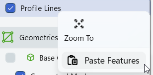
If you have an initial set of polylines stored in another vector layer, you can paste them into your Conceptual Mesh layer as new Arcs.
Adding Vector Layers
If you're having trouble adding or working with vector layers, check our Quick Start Guide, under the Adding Map Layers section.
Importing Arcs into your conceptual mesh will bring up the following dialog, showing the Arcs you're about to paste into the layer.
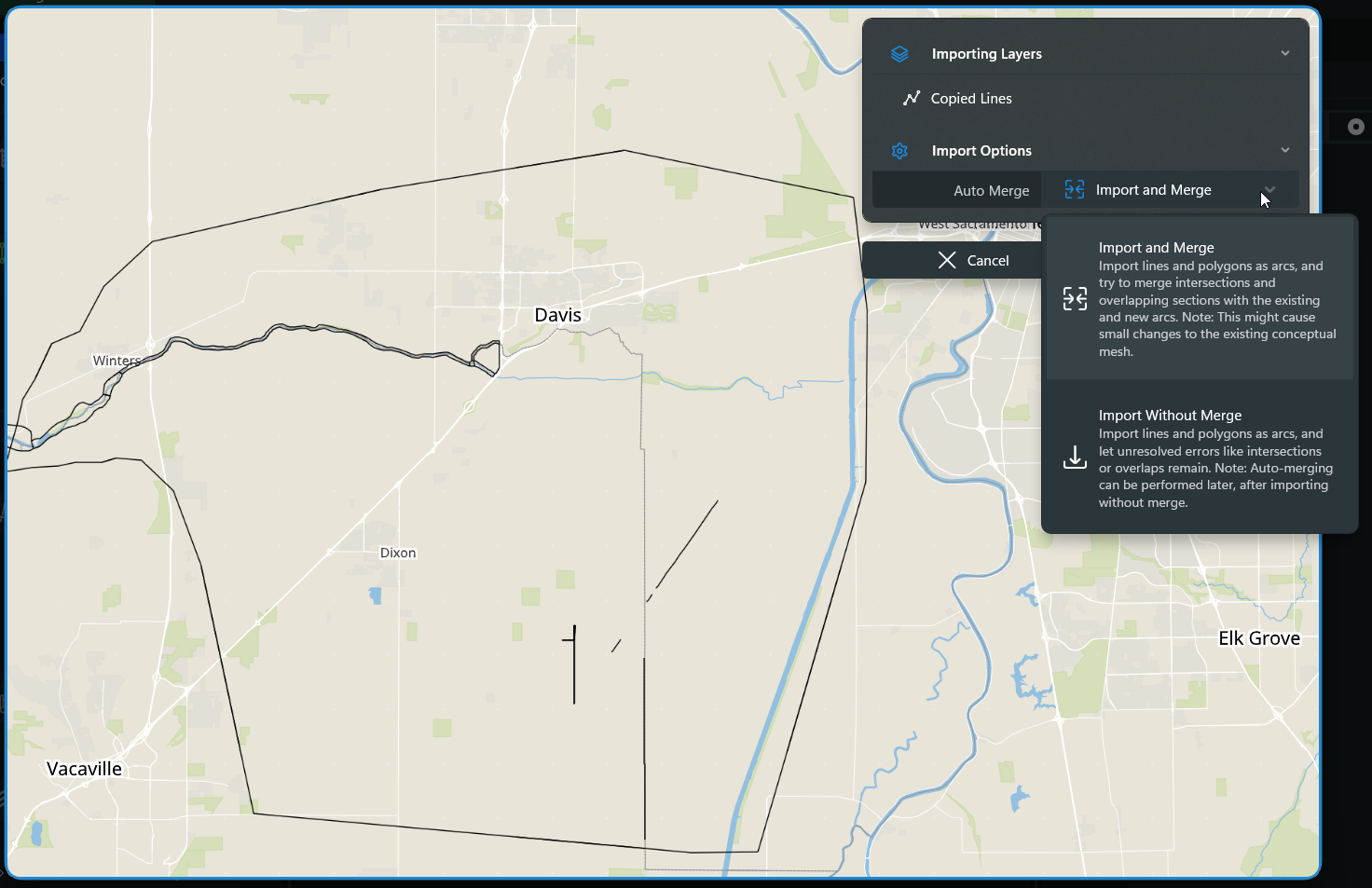
There are two available import options.
- Import and Merge: Pastes the Arcs into the mesh, reconciling intersections, duplicate Arcs, and other topological errors.
- Import without Merge: Pastes the Arcs into the mesh without any reconciliation/adjustment. The user must manually fix any resulting errors, or run the Fix Conceptual Mesh command.
Either option will paste your copied polylines as arcs in the conceptual mesh, giving them default mesh-generation properties.
Region Properties
Region properties control cell generation inside the conceptual mesh region. In the Components pane, regions have the following properties:
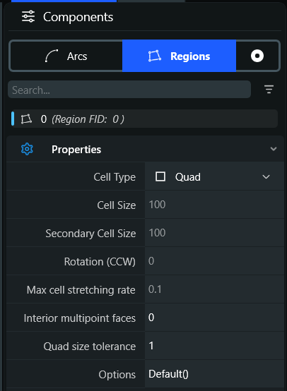
- Cell Type: Selects the type of cells generated in this region.
- Quad: Quadrilateral cells attempt to conform to a channel, with some understanding of lateral/longitudinal directions
- Triangular: Select this option to use triangular cells.
- Cartesian: Select this option to use cartesian (square) cells.
- Empty: Select this option to place a hole in your mesh - no computational cells will be generated in this region.
- Cell Size/Secondary Cell Size: Selects the cell spacing of the given cell type. This option is not available for Quad meshes, since arcs control the cell spacing for quadrilateral cells. Secondary cell size is only used to control an independent dy cell size for cartesian meshes.
- Rotation: This will rotate cartesian cell generation. Value is expressed as degrees CCW.
- Max cell stretching rate:
- Interior multipoint faces: Value is between 0 and 1. If set to 0, you get the left image (straight-line faces going downstream). If set to 1, you get the right image (curvilinear faces following the predicted flow-path downstream.)
- Quad size tolerance: In a quad region, increase/decrease the number of allowable triangles. Value is between 0 and 1.
- 0: Give me as many triangles as it takes to make my quads nice.
- 1: Only give me the triangles you absolutely must, to satisfy my quad spacing.
Interior Multipoint Faces & Triangles
(Documentation Pending)
Arc Properties
Arc properties generally control face generating and spacing along an arc. The following properties are available on your selected arc in the Components pane.
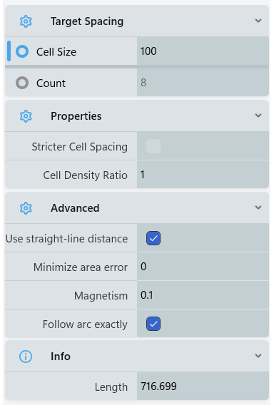
- Cell Size: Cell-size is the desired mesh cell-spacing along this arc. The option is mutually exclusive with Count.
- Count: Count is the desired number of mesh cells along this arc. We typically use this for the lateral axis in highly channelized quadrilateral regions. This option is mutually exclusive with Cell Size.
- Stricter Cell Spacing: Allows the arc to shrink its cell spacing to account for constraining neighboring arcs. If this option is on, the arc will more strictly enforce its cell spacing, even if it creates bad cells at a joint. If this option is off, the arc will adjust its spacing to create more uniform cells.
- Cell Density Ratio: Cell Density Ratio (sometimes called 'Bias') is the ratio of cell-sizes from the beginning to the end of the arc, which allows for variable cell distribution along it. A value of 1 has no bias (equal-sized cells at all points on the arc).
The following advanced options can be useful on high-curvature arcs. They generally balance the user's desired spacing and face enforcement against higher quality cells.
- Use straight-line distance: Uses the straight-line 'as a crow flies' distance for adding new cells (as opposed to the polyline distance following the arc). This option is only useful if your arc has a very high degree of polyline curvature compared to its cell size.
- Minimize area error:
- Magnetism: Computational nodes that land near an arc interior point will be magnetized to that point.
- Follow arc exactly: Set computational faces to strictly follow this arc. Defaults to on. When this setting is off, faces can deviate slightly from following tight arc curvature to preserve better numerical properties (orthogonality, cell growth) and emit fewer cells.
User Interface
We're still working on improved UI around these parameters, including better guidance, preview meshes, and in-map graphical editing. Look for these improvements in a future build!
Channels
Aligning Cells
(Documentation Pending)
Multipoint Faces
For highly channelized sections of your model with few cells across, it may be advantageous to use curved faces going downstream.
Expanding/Contracting Channels
If a quadrilateral channel is expanding or contracting, triangles will be inserted to step up/down the number of quads across the channel.
Overbanks
(Documentation Pending)
Mesh Generation Process
It can be helpful to understand the approximate mesh generation process, particularly when things are going wrong.
Step 1: Topology Completion
In the first stage of mesh generation, RAS has to build the full topology from the collection of individual arcs and nodes. RAS walks along these features to build a connectivity graph, checking for systematic errors (arc intersection, isolated nodes, etc.) along the way. Regions are derived from this process - they do not exist until we walk the connectivity graph and 'discover' completed rings. This presents a challenge for metadata tracking; if a user disconnects an arc from a node and reconnects it to an adjacent one, the two separated regions become a single region in that brief moment before the arc is reconnected. We have a couple of internal approaches to track and 'heal' metadata during this process and restore the user's original mesh intents, but they don't always work perfectly. If you lose mesh generation metadata (cell type and size) during arc edits, this is the principle reason why.
Step 2: Arcs generate faces
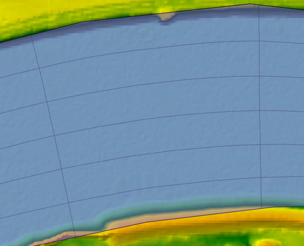
In stage 2, arcs generate computational mesh faces based on the chosen spacing, with some massaging around joints so they can work with neighboring arcs. Because arc faces are generated first, they can constrain the overall mesh cell spacing. While a mesh region may request 500ft cells, neighboring arcs set to use smaller cells (and limited cell growth rates) may limit the realized cell size to far less than that. We call this constraint the cell size function, and you can visualize it in the UI from the Layer tab with the Conceptual Mesh layer selected.
Step 3: Regions generate cells
In stage 3, mesh regions generate cells based on the region's background cell type and spacing. Cell generation is further constrained by the background size function. The mesh generation system will emit triangles as needed to grow or shrink to the target size function.
Step 4: Post-process correction/massaging
In stage 4, generated cells and faces shift to improve various computational mesh qualities, like orthogonality and cell-size growth rates. Other post-processing routines allow the user to collapse triangles and merge small faces. For a full list of post-processing routines, see the Post Processing section below.

Conceptual Mesh Errors
After building or importing Arcs into a conceptual mesh, it may return a number of errors. These are typically geospatial errors that need to be fixed before we can continue on with mesh generation. The offending area of the model will be highlighted in red, and a list of errors will be in the Layer tab.

Intersecting Arcs
Arcs may not intersect. If the intersection is not obvious, you may have to zoom into the map further to see small-scale features. This error may also occur when Arcs are coincident, e.g. when the same Arc is pasted into your layer twice.
To fix:
- Edit your topology to move the Arc internal vertices so they won't intersect.
- Insert a Node (ctrl+click) at the point of intersection.
- Delete unnecessary Arcs.
|
|
|


Hanging Arcs
Arcs that are 'hanging' outside of a mesh region (and cannot affect mesh generation) are not currently allowed.
To fix:
- Select and delete Arcs outside of your mesh generation area.
|
|


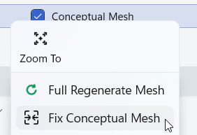
Auto-Fix Errors
Most of these errors can be fixed in an automated fashion, with the Fix Conceptual Mesh command. This will automatically insert Nodes to split any pair of intersecting Arcs. This can be destroy some mesh generation metadata (like cell-sizes), so be sure to check your mesh afterwards. This operation can be undone with ctrl+z.
Geospatial math with floating-point (decimal) values is inherently imprecise, leading to compounding errors in common operations like a "point in polygon" check. To mitigate this, our conceptual mesh fixer will proactively merge and connect arcs that are "close enough" to be potentially confused as an intersection (even if they don't precisely intersect). The definition of "close enough" is a constant battle to hit the right balance on the math vs user's intent. If you experience any issues where you believe the mesh 'fixing' created an error, please let us know with the bug reporter.
Mesh Generation Errors
This section is referring to 'computational' mesh errors, e.g. cell/face generation, breakline enforcement, etc.
Mesh generation errors are most common if the user has entered cell-sizes that are incompatible with the size and shape of the vector features. We're still working on improved UI and messaging in this area. If the mesh generation process fails, you will see a popup window that gives you the region(s) that failed to generate.
(Documentation Pending)
Post Processing
The new meshing system has a robust post-processor that gives users flexibility and control over their mesh design with a few instructions. A mesh post-processor is a set of cell and face manipulations that run after the basic mesh generation stage. This generally happens in two passes - one stage is independent per-region, and one stage is global to the entire mesh. Each post-processor recipe is comprised of many different steps. Currently, post-processors have limited UI support and must be typed in by hand. Post-processing steps use a function-like syntax, e.g. StepName(Argument1=Value, Argument2=Value, ...). The following steps are available on all regions.
Post-Processing Steps
SwapEdges
The SwapEdges step is specific to pairs of adjacent triangles. This stage will selectively replace their common face with a face connecting the two other face points.
- Candidate faces are chosen based on one of two tests:
threshold: the sum of the degree of the adjacent facepoints. A threshold of 14 means that a face with two facepoints both having 7 adjacent faces would be a candidate.shorten: a face is flipped if the new face would be shorter (added 2024-04-03, not yet pushed to master).- If both are specified, the degree threshold takes precedence.
- Face flips are not allowed to create a concave cell.
Smooth
The Smooth step replaces computational nodes with the average of their adjacent node locations, smoothing out sharp transitions. It has the following arguments:
- count (integer): The number of repeated passes. Higher values will do more smoothing, at the expense of mesh computation time.
- scaled (boolean): If true, adjust the smoothing to try to maintain the target length of faces. In areas of sharp gradients in the size function this generally gives better results. When false, a straight average of adjacent nodes is used.
- sliding (boolean): If true, smoothing will also apply to boundary nodes (along arcs). If false, only non-boundary nodes are adjusted. Even with sliding set to true, nodes will not be moved if a neighboring region is expected but not yet present. For example, when smoothing a region, nodes along a perimeter can be adjusted, but nodes shared by 2 regions will not be moved. If applied globally then nodes shared between two regions can be adjusted, but nodes of the conceptual mesh are still treated as fixed.
Ex: Smooth(count=10, scaled=true, sliding=true)
SmoothAngles
SmoothAngles applies Zhou and Shimada angle-based smoothing ("An Angle-based Approach to Two-dimensional Mesh Smoothing"). In some cases this may give a better result than length-based smoothing.
- count (integer): The number of smoothing iterations.
Ex: SmoothAngles(count=5)
Split
Split will split quads into two triangles based on an orthogonality threshold.
- threshhold (real): Threshold for splitting quads.
- 0.0 → All quads are split into triangles.
- .15 → Split quads that are visibly non-orthogonal.
- Larger values will split progressively fewer quads.
Ex: Split(threshold=.5)
Merge
Merge is the opposite of Split, and will combine adjacent triangles into a quadrilateral. Merges are performed starting with the smallest separation first, and proceed until there are no faces with a separation smaller than the threshold, or there are no pairs of adjacent triangles. Merges are not allowed to create concave cells.
- threshhold (real): Threshhold for merging quads. Uses the same definition as the Split command.
- 0.0 → merge pairs of obtuse triangles (for which the circumcenter separate is negative)
- Larger values create more quads
Ex: Merge(threshhold=.1)
MergeFaces
MergeFaces merges 4 cells around a node, producing 2 cells. This is not allowed to create cells with more than 4 faces, or produce concave cells. MergeFaces does not yet have any arguments.
Ex: MergeFaces()
Defaults
Default()
- Apply a predetermined recipe to the region that is specific to the region type (the recipes below may not be up to date)
- Quads
Smooth(count=10,scaled=true)Split(threshold=0.4)
- Hybrid quad
Smooth(count=10,scaled=false)Split(threshold=0.4)
- Triangles
SwapEdges()Smooth(count=10,scaled=true)Merge(threshold=0.0)Smooth(count=10,scaled=true)Split(threshold=0.1)
- Cartesian
SwapEdges()
Tips and Tricks
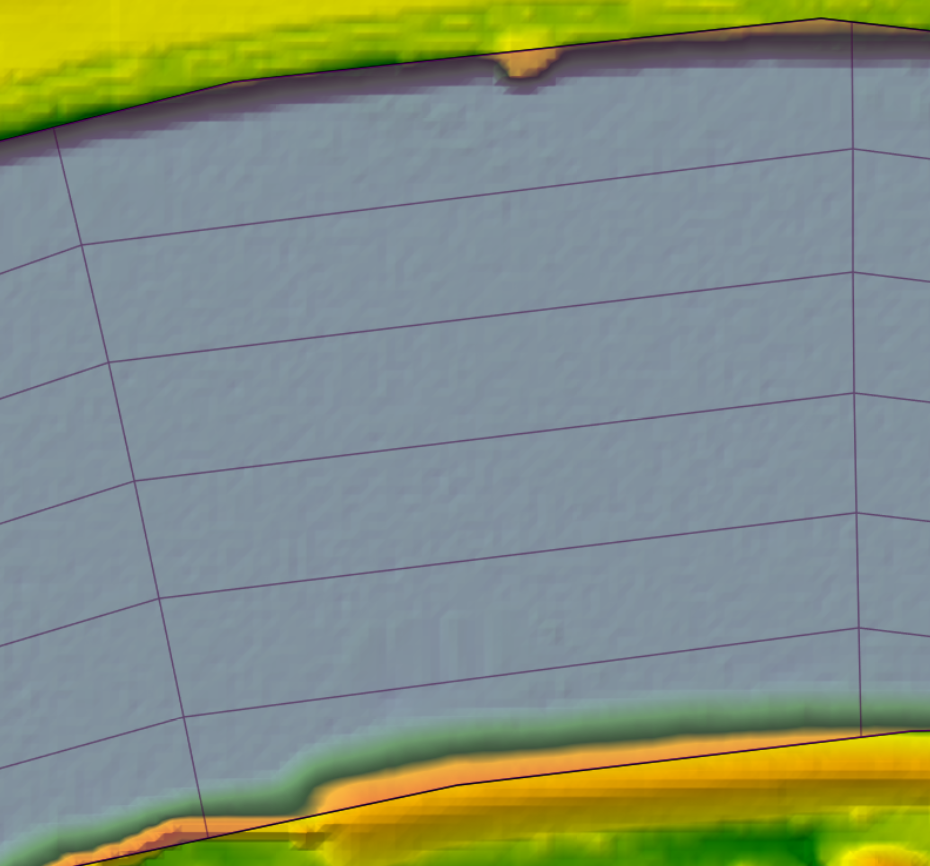
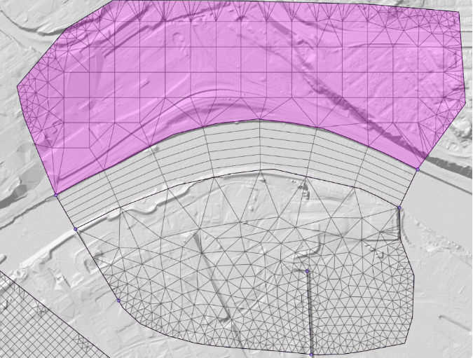
Cell stretching rates can prevent the mesh from building what you asked for, and it's not always intuitive why. Consider the following mesh, where the highlighted northern region is set to use cartesian cells, but is entirely filled with triangles.
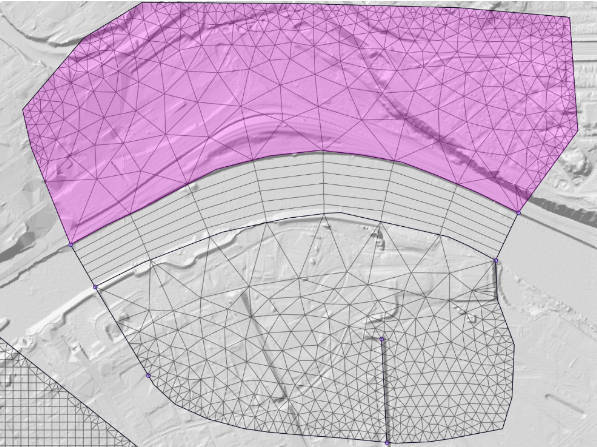
Our selected cell-sizes (800ft on the southern arc constrained by the channel, 100ft on the northern arc) alongside the default Max cell stretching rate of .1 over-constrain the problem. The meshing system tries to telescope down to the background cell-size where it can inject cartesian cells, but it can't get there fast enough. If we increase the Max cell stretching rate, we can see our cartesian cells (shown below). (Please note this example is for demonstration purposes. You should not arbitrarily change cell-size growth rates unless you're comfortable with the numerical error being introduced.)
Best Practices
(Documentation Pending)