This chapter describes how the reservoir element in HEC-HMS is used for modeling reservoirs or other types of water storage features, such as detention or retention ponds or natural lakes. Reservoirs have many uses, including flood mitigation, water supply, hydropower, and recreation. Reservoirs functionally change the hydrograph on a stream, allowing for inflowing water to be stored and then released at altered times and rates. Some reservoirs are operable and releases can be controlled, while others, such as detention ponds, may use an uncontrolled culvert or weir as a release structure. The primary objective of modeling reservoirs in HEC-HMS is to include how the reservoir changes the hydrologic response in a watershed.
A reservoir can mitigate downstream flooding and other adverse impacts of excess water by holding that water and releasing it at a rate that will not cause damage downstream. This is illustrated by the hydrographs shown in Figure 1. In this figure, the target flow (release from detention pond) is 113 units. The inflow peak is as shown in the figure; 186 units. To reduce this peak to the target level, the reservoir provides storage for the water. Thus the volume of water represented by the shaded area is stored and then released gradually. The total volume of the inflow hydrograph and the volume of the outflow hydrograph (the dotted line) are the same, but the time distribution of the runoff is altered by the storage facility.
Figure 2 is a sketch of a simple detention structure. The structure stores water temporarily and releases it, either through controlled or uncontrolled outlets the outlet pipe or over the emergency spillway. The configuration of the outlet works and the embankment in this illustration serves two purposes. It limits the release of water during a flood event, thus protecting downstream property from high flow rates and stages, and it provides a method of emptying the pond after the event so that the pond can store future runoff. (Structure operators also check that this change in timing of the peak does not adversely coincide with flows from other parts of the basin that are downstream of the detention structure.)
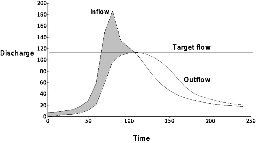
Figure 1.Illustration of the impact of detention.
The reservoir outlet may consist of a single culvert, as shown in Figure 2. It may also consist of separate conduits of various sizes or several inlets to a chamber or manifold that leads to a single outlet pipe or conduit. The rate of release from the reservoir through the outlet and over the spillway depends on the characteristics of the outlet (in this case, a culvert), the geometric characteristics of the inlet, the characteristics of the spillway, and the tailwater condition. The reservoir can also have an auxiliary spillway that releases to a different stream.
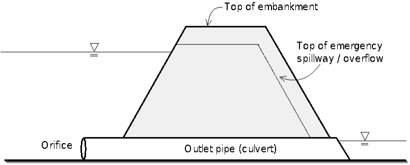
Figure 2.Simple detention structure.