Download PDF
Download page Basic Concepts and Equations.
Basic Concepts and Equations
While a reservoir element in HEC-HMS conceptually represents a natural lake or a lake behind a dam, the actual storage simulation calculations are performed by a routing method in conjunction with a storage method, contained within the reservoir.
Defining Routing
Outflow from an impoundment that has a horizontal water surface can be computed with the so-called level-pool routing model (also known as the Modified Puls routing model). That model discretizes time, breaking the total analysis period into equal intervals of duration Δt. It then recursively solves the following one-dimensional approximation of the continuity equation:
| I_{avg}-O_{avg}=\frac{\Delta S}{\Delta t} |
in which I_{avg} is the average inflow during time interval; O_{avg} is the average outflow during time interval; \Delta S is the storage change. With a finite difference approximation, this can be written as:
| \frac{I_t+I_{t+1}}{2}-\frac{O_t+O_{t+1}}{2}=\frac{S_{t+1}-S_t}{\Delta t} |
in which t is the index of time interval; I_t and I_{t+1} are the inflow values at the beginning and end of the t^{th} time interval, respectively; O_t and O_{t+1} are the corresponding outflow values; and S_t and S_{t+1} are the corresponding storage values. This equation can be rearranged as follows:
| (\frac{2S_{t+1}}{\Delta t}+O_{t+1})=(I_t+I_{t+1})+(\frac{2S_t}{\Delta t}-O_t) |
All terms on the right-hand side are known. The values of I_t and I_{t+1} are the inflow hydrograph ordinates, perhaps computed with models described earlier in the manual. The values of O_t and S_t are known at the tth time interval. At t = 0, these are the initial conditions, and at each subsequent interval, they are known from calculation in the previous interval. Thus, the quantity (\frac{2S_{t+1}}{\Delta t}+O_{t+1}) can be calculated with the equation above. For an impoundment, storage and outflow are related, and with this storage-outflow relationship, the corresponding values of O_{t+1} and S_{t+1} can be found. The computations can be repeated for successive intervals, yielding values O_{t+1}, O_{t+2}, ... O_{t+n}, the required outflow hydrograph ordinates.
Defining Detention (Storage)
To model storage within the reservoir element, the relationship between outflow and storage for the reservoir must be defined by the user. HEC-HMS can accept this relationship described in terms of storage-outflow, elevation-storage-outflow, or a combination of elevation-area-outflow with the elevation-storage relationship. The relationship that is developed and provided will depend on the available data, characteristics of the pond or reservoir, the outlet, and the spillway. Figure 3 illustrates how the relationship in a simple case might be developed. Hand calculations or a hydraulic model, like HEC-RAS, can be used develop storage-outflow relationships for complex structures.
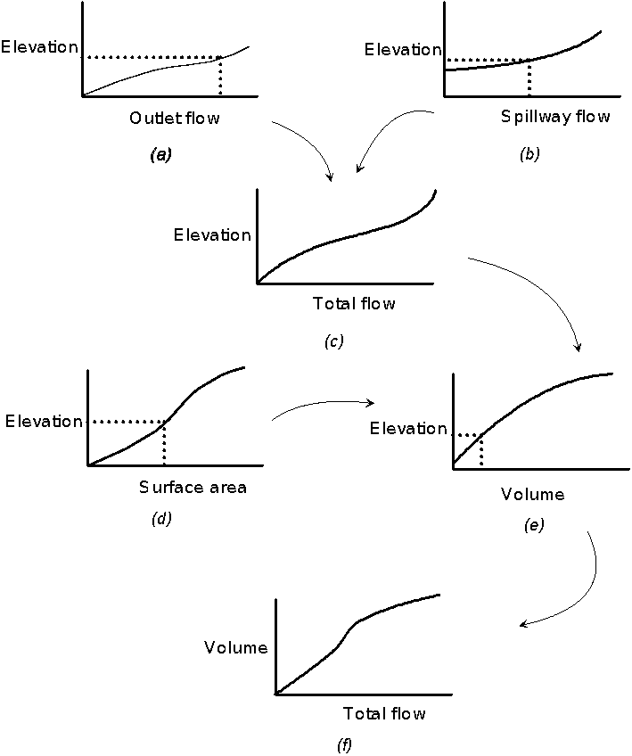
Figure 3.Illustration of the procedure for defining a storage-outflow relationship.
Figure 3(a) is the pond outlet-rating function; this relates outflow to the water-surface elevation in the pond. The relationship is determined with appropriate weir, orifice, or pipe formulas, depending on the design of the outlet. In the case of the configuration of Figure 2, the outflow is approximately equal to the inflow until the capacity of the culvert is exceeded. Then water is stored and the outflow depends on the head. When the outlet is fully submerged, the outflow can be computed with the orifice equations:
| O=KA\sqrt{2gH} |
in which O = flow rate; K = dimensional discharge coefficient that depends upon the configuration of the opening to the culvert; A = the cross-sectional area of the culvert, normal to the direction of flow; H = total energy head on outlet; and g is the gravitational constant. This head is the difference in the downstream water-surface elevation and the upstream (pond) water-surface elevation.
Figure 3(b) is the spillway rating function. In the simplest case, this function can be developed with the weir equation. For more complex spillways, refer to EM 1110-2-1603 (1965), to publications of the Soil Conservation Service (1985), and to publications of the Bureau of Reclamation (1977) for appropriate rating procedures.
Figure 3(a) and (b) are combined to yield Figure 3(c), which represents the total outflow when the reservoir reaches a selected elevation.
Figure 3(d) is relationship of reservoir surface area to water-surface elevation; the datum for the elevation here is arbitrary, but consistent throughout the figure. This relationship can be derived from topographic maps or grading plans. Figure 3(e) is developed from this with solid-geometry principles.
For an arbitrarily-selected elevation, the storage volume can be found in Figure 3(e), the total flow found in Figure 3(c), and the two plotted to yield the desired relationship, as shown in Figure 3(f). With this relationship, Equation x can be solved recursively to find the outflow hydrograph ordinates, given the inflow.
If storage is not known but the relationship for elevation-area is, the conic formula is used to estimate the volume in slices of the reservoir using elevation and area. The conic formula, as used to approximate storage, is expressed by the following equation:
| \Delta S=\frac{( elev_1-elev_2)}{3} (A_1+A_2+\sqrt{A_1 A_2 } ) |
where \Delta S is the incremental storage between two reservoir elevations (elev1 and elev2) and their respective sectional areas are A1 and A2. A limitation to this approach is that it does not work well for very large reservoirs, where the level pool assumption is not realistic.
The reservoir can have one or more inflows and computed outflows through one or more outlets. Assumptions include a level pool.