Basic Concepts and Equations
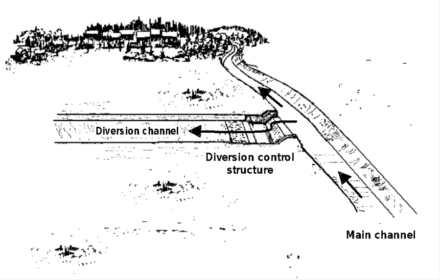
The Figure below is a sketch of a diversion. This diversion includes a bypass channel and a control structure (a broad-crested side-channel weir). When the water-surface elevation in the main channel exceeds the elevation of the weir crest, water flows over the weir from the main channel into the by-pass channel. The discharge rate in the diversion channel is controlled by the properties of the control structure. The discharge rate in the main channel downstream of the control is reduced by the volume that flows into the diversion channel.

A diversion is modeled in the same manner as a stream bifurcation by using a simple one-dimensional approximation of the continuity equation. In that case:
| 1) |
O_{t}^{main}=I_t-O_{t}^{bypass} |
in which O_{t}^{main}= average flow passing downstream in the main channel during time interval t ; I_t = average main channel flow just upstream of the diversion control structure during the interval; and O_{t}^{bypass}= average flow into the by-pass channel during the interval.
Setting Up a Diversion Model
The diversion model included in the program requires specifying the by-pass channel flow as a function of the main channel flow upstream of the diversion. That is represented as:
| 2) |
O_{t}^{main}=I_t-f(I_t) |
in which f(I_t) = the functional relationship of main channel flow and diversion channel flow. The relationship can be developed with historical measurements, a physical model constructed in a laboratory, or a mathematical model of the hydraulics of the structure. For example, flow over the weir in the above Figure can be computed with the weir equation:
in which = total energy head on crest. This head is the difference in the weir crest elevation and the water-surface elevation in the channel plus the velocity head, if appropriate. The channel water-surface elevation can be computed with a model of open channel flow, such as HEC-RAS. For more accurate modeling, a two-dimensional flow model can be used to develop the relationship.
Return Flow from a Diversion
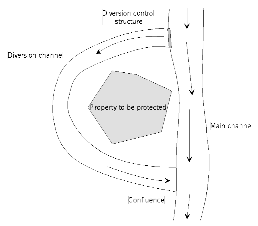
The bypass channel may be designed to return flow to the main channel downstream of the protected area, as illustrated in the Figure below. This is modeled in the program by linking a diversion/bifurcation model with channel routing models for the main and bypass channels and a confluence model at the downstream intersection of the bypass and main channels, as shown in the Figure below. Chapter 8 provides more information about modeling a confluence.

Applicability and Limitations of the Diversion Model
The diversion model is applicable to water-control systems in which the necessary relationship between main channel and bypass channel flow can be developed.
If a backwater condition can exist at the control structure (due to downstream conditions such as the confluence of the diversion and the main channel), then an unsteady-flow network model, such as HEC-RAS, must be used to properly represent the complex hydraulic relationship.