Download PDF
Download page Diversion Sediment.
Diversion Sediment
A Diversion Element is used to represent a hydraulic control structure that directs some of the stream flow out of the channel and into a storage pond or side channel. The Diversion Method calculates the amount of flow to be diverted and subtracts it from the inflow to the element. The diverted flow may be connected to a downstream location in the channel network. After the diverted flow is subtracted from the inflow, the remaining flow continues downstream through the channel network. Sediment is managed in much the same manner. The inflow to the diversion element is accompanied by sediment entering the element. Some of the sediment may be taken with the diverted flow. The remaining sediment continues downstream with the channel flow that passes through the diversion element. The physical properties of the diversion structure control the amount of sediment that goes with the diverted flow as compared to the amount of sediment remaining in the channel.
Selecting a Sediment Method
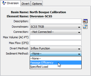
The Sediment Method for a diversion is selected on the Component Editor for the Diversion Element (shown in the following figure). Access the Component Editor by clicking the Diversion Element icon on the Components tab of the Watershed Explorer. You can also access the Component Editor by clicking on the element icon in the Basin Map, if the map is currently open. You can select a Sediment Method from the list of three available choices. If you choose the None method, the source will not compute any sediment and all sediment discharges from the element will be zero. Use the selection list to choose the method you wish to use. Each diversion is treated separately and should use an appropriate method for the configuration of the diversion structure and its ability to pass sediment with the diverted flow.

The parameters for each Sediment Method are presented on a separate Component Editor from the diversion element editor. The Sediment editor is shown next to the Divert editor once a Sediment Method has been selected. The information shown on the Sediment editor will depend on which method is currently selected.
Passage Efficiency
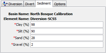
Diversion structures are usually designed primarily to control the movement of water, redirecting some portion of the inflow away from the main channel. In general, the d50 of the sediment in the diverted flow is smaller than the d50 of the sediment in the main channel. The Passage Efficiency Method provides a simple approach to controlling the differential sediment movement that typically occurs at diversion structures. The Component Editor is shown in the following figure.
The Clay Percentage in the diverted flow must be specified. The incoming clay load to the diversion element is converted to a concentration. Subsequently the clay concentration in the diverted flow is calculated as the incoming concentration multiplied by the specified percentage. A mass balance is then performed in order to calculate the load in the diverted flow and the load remaining in the channel. When the AGU 20 grain size classification is used, the same percentage is used for all subclasses of clay.

The Silt Percentage in the diverted flow must be specified. The silt percentage may be close to the clay percentage if the velocity through the diversion structure is high. When the AGU 20 grain size classification is used, the same percentage is used for all subclasses of silt.
The Sand Percentage in the diverted flow must be specified. Unless the diversion structure is specifically designed to direct sediment from the main channel, the sand percentage will be much smaller than the percentage for clay and silt. When the AGU 20 grain size classification is used, the same percentage is used for all subclasses of sand.
The Gravel Percentage in the diverted flow must be specified. The percentage for gravel is often close to zero. When the AGU 20 grain size classification is used, the same percentage is used for all subclasses of gravel.
Specified Load
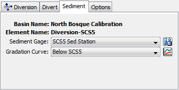
The Specified Sediment Method uses observed sediment load time-series data to determine the sediment to remove from the inflow to the diversion element and transfer with the diverted flow. Remaining sediment remains in the channel and continues to be routed downstream of the diversion. If observations of sediment are not available where the diverted flow is discharged out of the channel, then an external model could be used to compute the sediment load. The Component Editor is shown in the following figure.

The total sediment discharge for the diverted flow is specified with a Time-Series of Sediment Load. The time-series should represent the total of all grain size classes. The time-series data must be defined in the Time-Series Data Manager before it can be selected in the Sediment editor. The Time-Series button next to the selection list can be used to assist in selecting the correct sediment gage.
The total sediment discharge in the diverted flow is apportioned into grain size classes using a Grain Size Distribution Curve. The grain size distribution curve is specified with a diameter-percentage function. The function data must be defined in the Paired Data Manager before it can be selected in the Sediment editor. The Paired Data button next to the selection list can be used to assist in selecting the correct function.