Download PDF
Download page Selecting a Surface Method.
Selecting a Surface Method
The Surface is one of the components that can be included in the subbasin element. It is intended to represent the ground surface where water may accumulate in surface depression storage. The depression storage of an impervious surface such as a parking lot is generally close to zero. However, the depression storage for an agricultural field can be quite large if conservation tillage practices are used. Precipitation through-fall from the canopy, or direct precipitation if there is no canopy, impacts on the surface. The net precipitation accumulates in the depression storage and infiltrates as the soil has capacity to accept water. Surface runoff will begin when the precipitation rate exceeds the infiltration rate of the soil layer (loss method), and the surface storage is filled. The Dynamic Surface method does contain an option to simulate a layer on top of the soil, which has its own surface infiltration rate. Precipitation residing in the surface storage can infiltrate after precipitation stops and is subject to potential evapo-transpiration. Selecting a Surface Method is optional and generally only used for continuous simulation or post wild-fire applications.
The Dynamic Surface method is available for each subbasin element to account for post wildfire scenarios or other scenarios where a surface layer of vegetation and/or soil limits the amount of precipitation that is available to infiltrate into the soil layer. The main purpose of this dynamic surface capability is to model the recovery of infiltration over time after a fire which directly affects runoff generation and the implication for predicting flash floods and debris flows. The dynamic surface infiltration options allows you an option to model infiltration rates returning to their pre-fire rates resulting in reduced runoff over time as the watershed recovers from its burned state.
The Surface Method for a subbasin is selected on the Component Editor for the subbasin element as shown in the following figure. Access the Component Editor by clicking the subbasin element icon on the Components tab of the Watershed Explorer. You can also access the Component Editor by clicking on the element icon in the Basin Map, if the map is currently open. You can select a Surface Method from the list of three available choices. If you choose the None method, the subbasin will not compute any surface depression storage and all through-fall precipitation will be assumed as direct precipitation on the ground surface, and subject to infiltration into the soil. Use the selection list to choose the method you wish to use. Each subbasin may use a different method or several subbasins may use the same method.
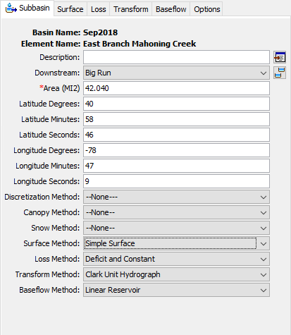
When a new subbasin is created, it is automatically set to use the default Surface Method specified in the Program Settings. You may change the Surface Method for a subbasin at any time using the Component Editor for the subbasin element. Since a subbasin can only use one Surface Method at a time, you will be warned when changing methods that the old parameter data will be lost. You can turn off this warning in the Program Settings. You can change the Surface Method for several subbasins simultaneously. Click on the Parameters menu and select the Surface | Change Method command. The Surface Method you choose will be applied to the selected subbasins in the Basin Model, or to all subbasins if none are currently selected.
The parameters for each Surface Method are presented on a separate Component Editor from the subbasin element editor. The Surface editor is always shown next to the Canopy editor. If the Kinematic Wave Transform Method is selected, there may be two Surface editors, one for each runoff plane. The information shown on the Surface editor will depend on which method is currently selected.
Gridded Simple Surface
This method implements the Simple Surface Method on a grid cell basis. Each grid cell has separate parameter values, and separate precipitation through-fall. The Component Editor is shown below.
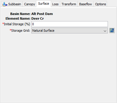
The initial condition of the surface should be specified as the Percentage of the Surface Storage that is full of water at the beginning of the simulation. The same percentage will be applied to every grid cell.
The Surface Storage Grid must be selected from the grids that have been previously defined in the Grid Data Manager. The grid should specify the maximum surface storage in each grid cell. You may use a chooser to select the grid by pressing the Grid button next to the selection list. You will not be able to select a grid if no grids have been created in the Grid Data Manager.
Simple Surface
This method is a simple representation of the soil surface. All precipitation or precipitation through-fall that arrives on the soil surface is captured in storage until the storage capacity of the surface is filled. Water in surface storage infiltrates into the soil whenever it is present in storage. That is, water will infiltrate even when the storage capacity is not full. Surface runoff will be generated when the storage capacity is filled, and the precipitation through-fall rate exceeds the infiltration rate. The Component Editor is shown below.
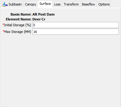
The initial condition of the surface should be specified as the Percentage of the Surface Storage that is full of water at the beginning of the simulation.
Surface Storage represents the maximum amount of water that can be held on the soil surface before surface runoff begins. The amount of storage is specified as an effective depth of water.
Dynamic Surface
The Dynamic Surface method includes a variable surface infiltration rate limit which can be computed from three surface infiltration limit options. The surface infiltration rate limit represents the hydrophobic layer that can form after a watershed burn as a result of lower organic material and changes in soil water repellency. The hydrophobic soil layer moderates the amount of water that is available for infiltration into the soil. The surface infiltration rate limit eventually returns to the pre-fire infiltration rate of the soil. Another application of the surface infiltration limit option is that it can be used to set an upper limit to the amount of losses computed from a subbasin element. For example, the deficit and constant loss method includes both a moisture deficit state variable and constant loss rate parameter. The moisture deficit simulates how much water, or lack of water, is in the soil layer. All precipitation is applied to reducing the moisture deficit until it reaches 0 inches/mm, then the constant loss rate is used to determine excess and infiltration/percolation. You can have a scenario where the moisture deficit is high, over 4 inches, and an intense precipitation rate of 1 inch/hour and HEC-HMS will not compute any excess precipitation (because the moisture deficit has not reached 0 inches). In this case, the Dynamic Surface infiltration limit option could be used to set an upper limit on infiltration losses so that there is runoff even though the moisture deficit is still greater than 0 inches.
This surface layer is conceptualized in the figure below.
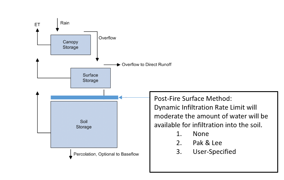
Precipitation that is not captured by canopy will interact with the Dynamic Surface layer. Some of the precipitation could be stored on the surface and lost to evaporation. The remaining precipitation will infiltrate through the top hydrophobic soil layer at a reduced rate. Precipitation that is not stored by the canopy or surface storage and is in excess of the surface layer's infiltration rate limit is transformed to runoff. The infiltrated water will enter the soil layer at the rate determined by the hydrophobic soil layer. The soil layer can store the water, evaporate the water, or further infiltrate/percolate for baseflow. There are three surface Infiltration Limit methods available for the Dynamic Surface method: Pak & Lee, Specified (Time Series), and None option. In the None option for the surface Infiltration Limit method, all water on the surface will be available for infiltration into the soil layer and functions the same as the Simple Surface method.
Pak & Lee Infiltration Limit
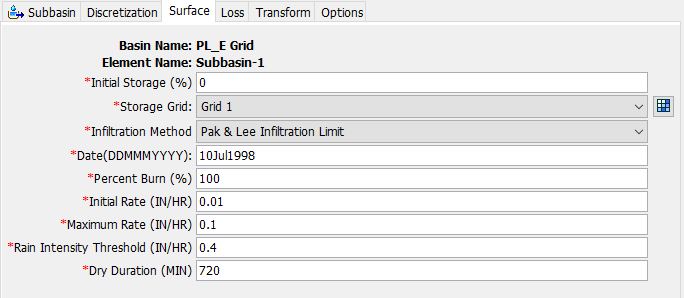
The Dynamic Surface Pak & Lee Dynamic Infiltration Limit method was developed based on the Pak & Lee fire factor equation generated using the percentage of the watershed burned, the number of years since the fire, and the number of antecedent precipitation events above a certain threshold value since the fire (Pak & Lee 2005). The Pak & Lee Infiltration Limit method is a simple process used to predict the temporal and spatial variations of an infiltration rate. The surface infiltration limit is calculated based on the date of the last fire, the percent burn (of the subbasin), and the number of preceding storm events. An event is defined when the precipitation intensity exceeds a user-specified threshold. A dry duration is used to separate precipitation events. Since the number of events is determined using precipitation data for each time step, the surface infiltration rate limit will be updated each simulation time step. The Component Editor, when using Pak & Lee Infiltration Limit method, is shown in the figure below.
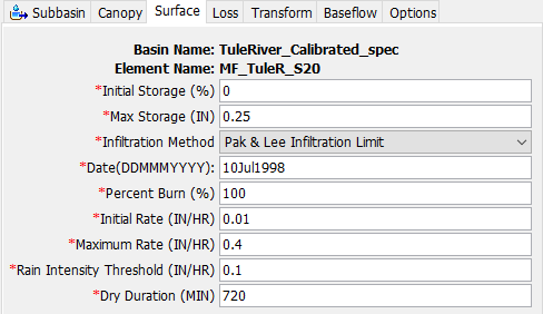
The Initial Storage represents the initial condition of the surface layer and is specified as a percentage of the surface storage that is full of water at the beginning of the simulation.
The Max Storage represents the maximum amount of water that can be held on the surface before surface runoff begins. The amount of storage is specified as an effective depth of water.
The Date is the burn date of the wildfire within the watershed.
The Percent Burn is the percent of the subbasin area that was burned from the wildfire.
The Initial Rate is the initial surface infiltration rate limit value as a result of the fire.
The Maximum Rate is the max surface infiltration rate limit value after the watershed has recovered.
The Rain Intensity Threshold is the rain intensity threshold that is used to define when an event occurs.
The Dry Duration is used to define separate precipitation events. Precipitation events are considered separate events once the duration with no precipitation exceeds the dry duration.
Specified Infiltration Limit (Time-Series)
The Specified Infiltration Limit method allows users to define the initial surface infiltration limit and a time series gage, a percent gage, which can be used to modify the surface infiltration limit rate. For example, the Initial Rate can represent the surface infiltration limit prior to a fire and the values in the Percent Gage can represent reduction to the surface infiltration limit due to fire conditions. The values in the Percent Gage could allow the surface infiltration limit to recover over successive years to the original pre-fire rate. The Component Editor, when using Specified Infiltration Limit method, is shown in the figure below.
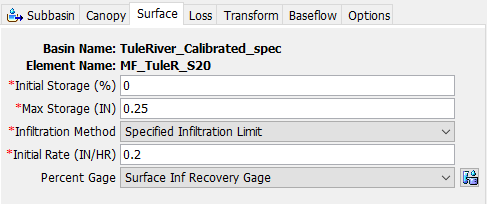
The Initial Storage represents the initial condition of the surface layer and is specified as a percentage of the surface storage that is full of water at the beginning of the simulation.
The Max Storage represents the maximum amount of water that can be held on the surface before surface runoff begins. The amount of storage is specified as an effective depth of water.
The Initial Rate is the initial surface infiltration rate limit value, and it could represent the post-fire condition (values in the percent gage should recover the infiltration rate limit to a pre-fire condition).
The Percent Gage requires users to create a Percent Time-Series gage. The time-series values are entered as percent and should overlap with the simulation period. This gage provides the percent factor to be applied to the initial rate limit for the given date to define the modified surface infiltration limit.
Gridded Dynamic Surface
The Gridded Dynamic Surface method essentially implements the Dynamic Surface method but the Max Storage is replaced with a Storage Grid, similar to the Gridded Simple Surface method. Each grid cell has a separate max storage parameter value. The Gridded Dynamic Surface also includes the same three surface Infiltration Limit methods, Dynamic Surface: Pak & Lee, Specified (Time Series), and None option; however, these parameters do not vary by grid cells. The Pak & Lee Infiltration Limit and Specified Infiltration Limit methods are shown in the figures below.
