Download PDF
Download page Program Screen.
Program Screen
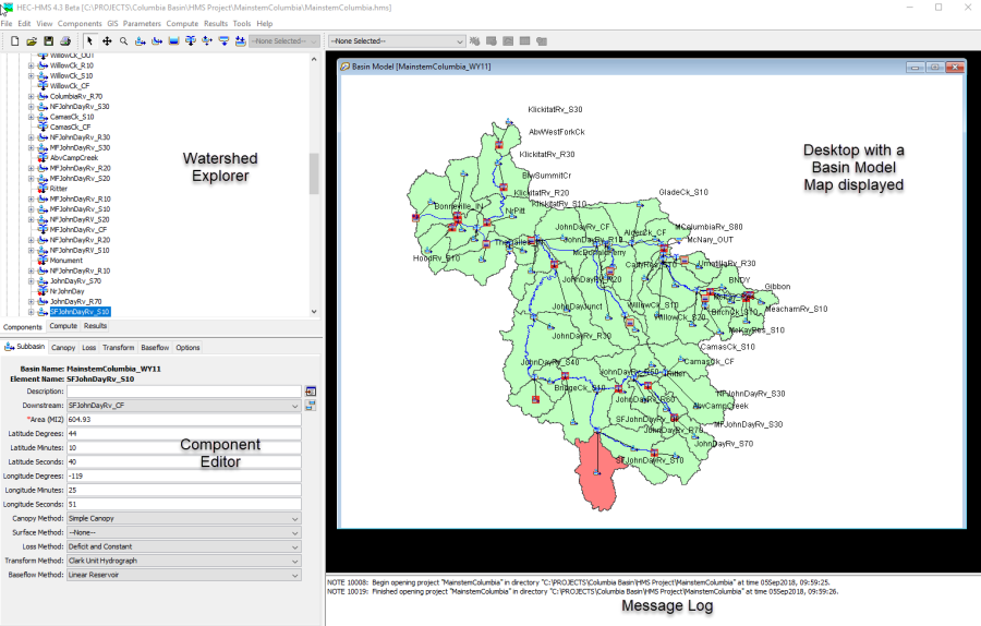
The program screen contains a title bar, menu system, toolbar, and four panes. These panes will be referred to as the Watershed Explorer, Desktop, Component Editor, and the Message Log as shown in Figure 1. The title bar displays the version of the program used and the location of the currently-open project. The other parts of the program screen are discussed in detail in this chapter.
Menu System
The menu system contains several menus to help you use the program. Each menu contains a list of related commands. For example, the Parameters menu contains a list of commands to open global parameter tables for viewing and editing parameters required by hydrologic elements in the selected basin model. Items in an individual menu are inactive (cannot be selected) if the command can not be carried out by the program at the current time.
Commands for managing the opened project are available from the File menu. File menu items and the resulting actions are provided in Table 1. The last four projects opened are shown at the bottom of the File menu. Click on one of the project names to open the project.
The Edit menu contains commands for editing hydrologic elements in the selected basin model. If no basin model is selected, then all commands in this menu are inactive. Edit menu commands and the resulting actions are provided in Table 2. Additional Edit menu includes commands select mouse tools for use in the Basin Model Map.
The View menu contains a list of commands for working in the basin map. These commands are inactive if no basin model is open in the Desktop. A list of View menu items and the resulting actions are provided in Table 3.

Table 1. Commands available from the File menu.
File Menu Commands | Action |
New… | Create a new project. |
Open… | Open a project. |
Import → | Import HEC-1 files, simulation run components, and individual components. |
Save | Save the current project. |
Save As… | Make a copy of the current project. |
Delete | Delete the current project. |
Rename | Rename the current project. |
Print… | Print the currently selected item. |
Exit | Exit the program. |
Table 2. Commands available from the Edit menu.
Edit Menu Commands | Action |
Cut | Cut or delete the selected hydrologic element(s). |
Copy | Make a copy of the selected hydrologic element(s). |
Paste | Paste the copied hydrologic element(s). |
Select All | Select all hydrologic elements in the basin model. |
Select Upstream | Select all hydrology elements located upstream of the selected element. |
Invert Selection | Select all elements not currently selected while unselecting the currently selected elements |
Clear Selection | Unselect all selected hydrologic elements in the basin model. |
Select By Name | Open the Select By Name dialog. |
Table 3. Commands available from the View menu.
View Menu Commands | Action |
Map Layers… | Open the map layers editor. |
Zoom In | Zoom in by a factor of 25%. |
Zoom Out | Zoom out by a factor of 50%. |
Zoom To Selected | Zoom to the current element selection. |
Zoom To All | Zoom out to the maximum extents. |
Draw Element Labels | Toggle showing of labels in different formats. |
Draw Flow Directions | Toggle flow direction arrows on reach elements. |
Toolbars | Toggle the file, components, and compute toolbars. |
Clear Messages | Clear all messages from the message window. |
Table 4. Commands available from the Components menu.
Components Menu Commands | Action |
Create Component | Open the basin model manager. |
Basin Model Manager | Open the basin model manager. |
Meteorologic Model Manager | Open the meteorologic model manager. |
Control Specifications Manager | Open the control specifications manager. |
Time-Series Data Manager | Open the time-series data manager. |
Paired Data Manager | Open the paired data manager. |
Grid Data Manager | Open the grid data manager. |
| Terrain Data Manager | Opens the terrain data manager. |
| Grid Region Manager | Open the grid region manager. |
Component managers are opened from the Components menu. Program components include grid regions, basin models, meteorologic models, control specifications, time-series data, paired data, and gridded data. A list of Components menu items and the resulting actions are provided in Table 4.
Table 5. Commands available from the GIS menu.
GIS Menu Commands | Action |
| Coordinate System | View or set the basin model coordinate system. |
| Preprocess Sinks | Run the sink preprocessing step of the watershed delineation workflow. |
| Preprocess Drainage | Run the flow direction and flow accumulation steps of the watershed delineation workflow. |
| Identify Streams | Run the stream identification step of the watershed delineation workflow. |
| Break Points Manager | Open the break points manager. |
| Delineate Elements | Complete the watershed delineation workflow by creating subbasin and reach elements. |
| Split Element | Split a selected subbasin or reach element at a point. |
| Merge Elements | Merge two selected subbasin or reach elements. |
| Reverse Flow Direction | Reverse the flow direction of a reach element. |
| Georeference Existing Elements | Georeference existing subbasin or reach elements using GIS files. |
| Import Georeferenced Elements | Import hydrologic elements from a GIS file. |
| Export Georeferenced Elements | Export subbasin or reach elements created using the watershed delineation workflow. |
The GIS menu contains menu commands to set the coordinate system of the basin model, perform watershed delineation tasks, and georeferencing basin model elements, as listed in Table 5. Once the coordinate system has been set using the Coordinate System command, subbasin, reservoir, and reach elements can be georeferenced using tools that are opened by selecting the Georeference Existing Elements and Import Georeferenced Elements menu options. Setting the coordinate system and georeferencing elements is optional. Only the HMR 52 Storm precipitation method requires subbasin elements to be georeferenced. One advantage to georeferencing elements is that that the elements are drawn using polygons and polylines in the basin model map. You can display the elements using icons and lines, GIS features, or both. The remaining menu commands are related to watershed delineation. The Preprocess Sinks, Preprocess Drainage, Identify Streams, and Delineate Elements commands are functions that create transformations of terrain data in order to create a basin model. Break Points Manager allows the user to manage break point elements needed for the delineation process. Split Element and Merge Elements can be used on subbasin and reach elements that have been created using the delineation process. Export Georeferenced Elements allows the user to export subbasin and reach elements created using the delineation process. Commands will only be available if prerequisite steps have been taken and the data necessary to perform the commands are available.
The Parameters menu contains menu commands to open global parameter editors. Global parameter editors let you view and edit subbasin and reach parameters for elements using the same methods (subbasin canopy, surface, loss, transform, and baseflow methods and reach routing and gain/loss methods). Global parameter menu options are only active if subbasin or reach elements in the basin model use the method. For example, if the Parameter | Loss menu option is selected, a submenu with all loss methods opens. Only loss methods used by subbasin elements in the current basin model will be active in the menu. If hydrologic elements are selected in the basin model, then the selected elements determine what menu items are available. The Parameters menu also contains menu commands to change subbasin canopy, surface, loss, transform, and baseflow methods and reach routing and gain/loss methods. If subbasin or reach elements are selected in the basin model, then only the selected elements will change methods. The last menu command on the Parameters menu is Element Inventory. This command lets you view a table of all hydrologic elements in the basin model. If elements are selected, then only the selected elements will be included in the table.
The Compute menu contains a list of commands for creating, computing, and managing simulation runs, optimization trials, analyses, and forecast alternatives. A list of Compute menu items and the resulting actions are provided in Table 6. Menu commands for creating simulation runs, optimization trials, forecast alternatives, depth-area analyses and uncertainty analyses are only enabled with the necessary underlying components have been created. The Compute command is only enabled when a compute item is selected.
The Results menu contains a list of commands for viewing results from hydrologic elements in a basin model. Three cases must be met before commands from the Results menu are active:
- A simulation run, optimization trial, analysis, or forecast alternative must be selected.
- A hydrologic element or elements must be selected.
- The results for the simulation must be available.
Results for a simulation are available as long as the simulation computed successfully and no changes were made by the user to components used by the simulation after it was computed. If you change parameter data, like values in a paired data table used by a reach element for modified-Puls routing, then the simulation must be recomputed. A list of Results menu items and the resulting actions are provided in Table 7.
Table 6. Commands available from the Compute menu.
Compute Menu Commands | Action |
Create Compute | Open a wizard to create a new simulation from among the five types. |
Simulation Run Manager | Open the simulation run manager to create, copy, rename, or delete runs. |
Optimization Trial Manager | Open the optimization trial manager. |
Forecast Alternative Manager | Open the forecast alternative manager. |
Depth-Area Analysis Manager | Open the depth-area analysis manager. |
Uncertainty Analysis Manager | Open the uncertainty analysis manager. |
Run Calibration Aids | When a run is selected, opens the calibration aids at a computation point. |
Forecast Initial Baseflow | When a forecast is selected, choose observed flow for automatically initializing subbasin baseflow |
Forecast Initial Reach Outflow | When a forecast is selected, choose observed flow for automatically initializing reach flow |
Forecast Parameter Adjustments | When a forecast is selected, opens the editor for loss rate and other adjustments. |
Forecast Slider Adjustments | When a forecast is selected, choose parameter adjustments for control by a slider. |
Forecast Slider Settings | When a forecast is selected, sets boundary range for each slider. |
Forecast Reservoirs | When a forecast is selected, choose observed stage for automatically initializing and adjusting reservoir storage. |
Forecast Blending | When a forecast is selected, opens the editor for observed flow blending. |
Multiple Compute | Compute multiple simulations sequentially. |
Table 7. Commands available from the Results menu. Items marked with (1) are available for simulations runs, items with (2) are available for optimization trials, and items with (3) are available for depth-area analyses.
Results Menu Commands | Action |
Global Summary Table1 | Open a summary table containing all hydrologic elements in the basin model. |
Objective Function Summary2 | Objective function value and statistics. |
Optimized Parameters2 | Optimized parameter values. |
Hydrograph Comparison2 | Comparison of computed and observed hydrographs. |
Flow Comparison2 | Computed versus observed flow values. |
Flow Residuals2 | Residual between computed and observed values. |
Objective Function2 | Objective function value by iteration. |
Peak Flow Table3 | Peak flow at analysis points. |
Element Graph | Open a graph of results for the current selection. |
Element Summary Table | Open a summary table for the current selection. |
Element Time-Series Table | Open a time-series table for the current selection. |
Graph Properties | Change the line styles, symbols, and other properties of the selected graph. |
The Tools menu offers a list of specialized commands. A list of Tools menu items and the resulting actions are provided in Table 8. Additional tools will be added to the menu in a future program version.
The Help menu provides links to the online help system. The sample projects can be installed from this menu. You may also access the terms and conditions for using the program, and information about the program and development team; this information is helpful when reporting program problems.
Table 8. Commands available from the Tools menu.
Tools Menu Commands | Action |
Reach Table → | View and edit paired data functions for elevation-discharge, elevation-area, and elevation-width. |
Reservoir Tables → | View and edit paired data functions for elevation-discharge and storage-discharge. |
Parameter Sample Creator | Convert the equilibrium sample from an Optimization Trial using the MCMC search. |
Reports → | Generate reports of basin model or simulation run results using a custom template. |
Delete Results | Delete time-series results for simulations. |
Program Settings | Change properties for the program. |
Toolbar
Like the menu system, the toolbar groups tools with similar uses. Also, tools are inactive if the resulting action for the tool can not be carried out by the program. Table 9 contains a description of tools on the toolbar.
Table 9. Description of the tools in the toolbar.
Tool | Action |
| Create a new project. |
| Open an existing project. |
| Save the current project. |
| Print the selected item in the Desktop (basin map or result window). |
| Select hydrologic elements in the basin map. |
| Add a subbasin element to the basin map. |
| Add a reach element to the basin map. |
| Add a reservoir element to the basin map. |
| Add a junction element to the basin map. |
| Add a diversion element to the basin map. |
| Add a source element to the basin map. |
| Add a sink element to the basin map. |
| Add a break point element to the basin map. |
| Compute the currently selected simulation run. |
| Compute the currently selected optimization trial. |
| Compute the currently selected forecast alternative. |
| Compute the currently selected depth-area analysis. |
| Compute the currently selected uncertainty analysis. |
| Open global summary table. |
| Open graph for the current element selection. |
| Open summary table for the current element selection. |
| Open time-series table for the current element selection. |
Watershed Explorer
The Watershed Explorer was developed to provide quick access to all components and simulations in a project. For example, the user can easily navigate from a basin model to a precipitation gage and then to a meteorologic model without using menu commands or opening additional windows. The Watershed Explorer is divided into three parts: Components, Compute, and Results.
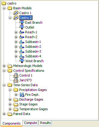
A typical view of the "Components" tab of the Watershed Explorer is shown in Figure 2. The hierarchical structure of model components, such as basin models, meteorologic models, etc., is available from the "Components" tab. The Watershed Explorer organizes model components into individual folders. If all component types were in a project, then the Components tab would contain seven main folders, Grid Regions, Basin Models, Meteorologic Models, Control Specifications, Time-Series Data, Paired Data, and Grid Data. The Watershed Explorer expands when one of these main component folders is selected. When a component in a main folder is selected, the Watershed Explorer expands even more to show sub-components. For example, when the Basin Models folder is selected, the Watershed Explorer expands to show all basin models in the project. The Watershed Explorer will expand again to show all hydrologic elements in a basin model when a basin model is selected. Notice in Figure 2 that the Castro 1 basin model is selected and the Watershed Explorer is expanded to show all hydrologic elements in the basin model. The plus/minus sign beside model components and sub-components can be used to expand or collapse the Watershed Explorer. The "Compute" tab of the Watershed Explorer contains all project simulation runs, optimization trials, analyses, and forecast alternatives. Model results are available from the "Results" tab of Watershed Explorer.

Desktop
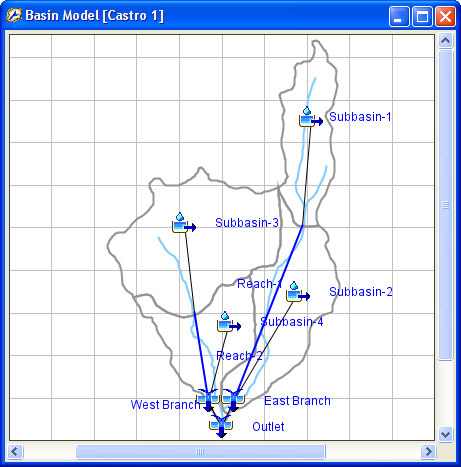
The Desktop holds a variety of windows including global parameter editors, and most importantly the basin map. Result windows including graphs, summary tables, and time-series tables can be shown in the Desktop, or optionally, outside the Desktop. All other windows cannot be moved outside of the Desktop area. The basin map is used to develop a basin model. Hydrologic elements (subbasin, reach, reservoir, etc.) are added from the toolbar and connected to represent the physical drainage network of the study area. Background maps can be imported to help visualize the watershed. The Castro 1 basin map is shown in Figure 3.
Component Editor
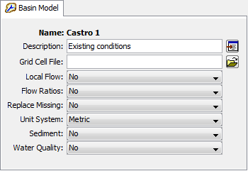
When a component or sub-component in the Watershed Explorer or hydrologic element in the basin map is active (use the mouse and click on the component name in the Watershed Explorer or select the hydrologic element in the basin map), a specific component editor will open. Data for model components is entered in the Component Editor. Required data is indicated with a red asterisk. For example, loss parameter data for a subbasin element is entered in the Component Editor for the subbasin. The Component Editor for the Castro 1 basin model is shown in Figure 4.


Message Log
Notes, warnings, and errors are shown in the Message Log, as seen in Figure 5. These messages are useful for identifying why a simulation run failed or why a requested action, like opening a project, was not completed.
