Download PDF
Download page Selecting a Transform Method.
Selecting a Transform Method
While a subbasin element conceptually represents infiltration, surface runoff, and subsurface processes interacting together, the actual surface runoff calculations are performed by a transform method contained within the subbasin. A total of eight different transform methods are provided. The choices include various unit hydrograph methods, a kinematic wave implementation, and a linear quasi-distributed method.
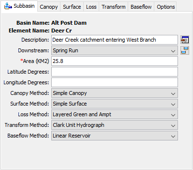
The transform method for a subbasin is selected on the Component Editor for the subbasin element as shown in Figure 1. Access the Component Editor by clicking the subbasin element icon on the "Components" tab of the Watershed Explorer. You can also access the Component Editor by clicking on the element icon in the basin map, if the map is currently open. You can select a transform method from the list of seven available choices. If you choose the None method, the subbasin will transform all excess precipitation as runoff at the end of each time step. Use the selection list to choose the method you wish to use. Each subbasin may use a different method or several subbasins may use the same method.
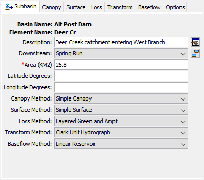
When a new subbasin is created, it is automatically set to use the default transform method specified in the program settings. You may change the transform method for a subbasin at any time using the Component Editor for the subbasin element. Since a subbasin can only use one transform method at a time, you will be warned when changing methods that the old parameter data will be lost. You can turn off this warning in the program settings. You can change the transform method for several subbasins simultaneously. Click on the Parameters menu and select the Transform | Change Method command. The transform method you choose will be applied to the selected subbasins in the basin model, or to all subbasins if none are currently selected.
The parameters for each transform method are presented on a separate Component Editor from the subbasin element editor. The "Transform" editor is always shown near to the "Loss" editor. The kinematic wave method uses multiple tabs in the Component Editor. The information shown on the transform editor will depend on which method is currently selected.
Clark Unit Hydrograph Transform
The Clark unit hydrograph is a synthetic unit hydrograph method. This means that the user is not required to develop a unit hydrograph through the analysis of past observed hydrographs. Instead, a time versus area curve (time-area curve) is used to develop the translation hydrograph resulting from a burst of precipitation. The resulting translation hydrograph is routed through a linear reservoir to account for storage attenuation effects across the subbasin. There are three methods available for the Clark unit hydrograph: Standard, Variable Parameter, and Maricopa County AZ USA. The Component Editor will automatically update based on the selected method.
Standard
The Component Editor, when using the Standard method, is shown in Figure 2.
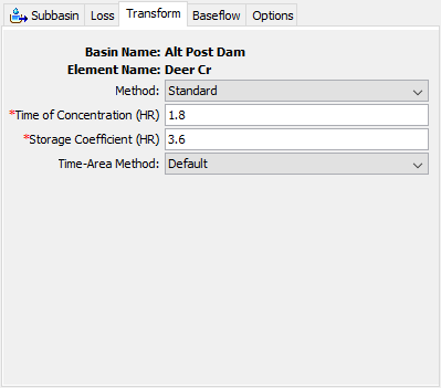
The time of concentration defines the maximum travel time in the subbasin. It is used in the development of the translation hydrograph.
The storage coefficient is used in the linear reservoir that accounts for storage effects. A dimensionless ratio can be defined as the storage coefficient divided by the sum of the time of concentration and storage coefficient. Many studies have found that the dimensionless ratio is relatively constant over a region.
Variable Parameter
Unit hydrograph theory assumes a linear relationship between precipitation and the runoff response. This assumption can lead to errors in timing and peak magnitude when simulating events that result from extremely large excess precipitation rates, such as the Probable Maximum Precipitation. When using the Clark unit hydrograph, tables relating time of concentration and storage coefficient to the excess precipitation can be used to vary the runoff response throughout the simulation. The Component Editor, when using the Variable Parameter method, is shown in Figure 3.
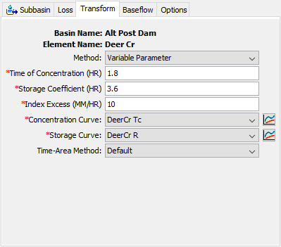
The "Index Excess" is an excess precipitation rate that is used to relate the time of concentration and storage coefficient defined in the editor against the variable parameter relationships. Typically, this rate is 1 inch/hour (or 1 mm/hour).
The variable parameter relationships must be defined as percentage curves in the paired data manager before they can be used in the subbasin element. These curves must be monotonically increasing. The x-axis of the percentage curves defines the excess precipitation rate relative to the index excess. The y-axis of the percentage curves defines either the time of concentration or storage coefficient for each percent excess precipitation rate (again, relative to the index excess).
The default time-area curve represents the subbasin using an elliptical shape. This shape has been shown to approximate the timing of surface runoff very well for typical subbasins. However, there is also an option to provide a user-specified time-area curve. The relationship must be defined as a percentage curve in the paired data manager before it can be used in the subbasin element. The independent axis of the percentage curve defines the percentage of the time of concentration, while the dependent axis of the curve defines the cumulative percentage of subbasin area contributing runoff. The curve must be monotonically increasing.
Maricopa County AZ USA
The Component Editor, when using the Maricopa County AZ USA method, is shown in Figure 4.
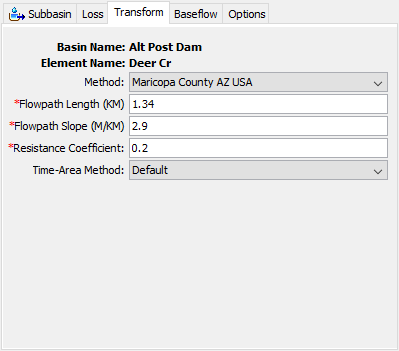
The Clark time of concentration and storage coefficient parameters are automatically computed using physical characteristics of the watershed and Equations 1 and 2.
| 1) | T_{c}=11.4 L^{0.5} K_{b}^{0.52} S^{-0.31} i^{-0.38} |
| 2) | R=0.37 T_{c}^{1.11} A^{-0.57} L^{0.80} |
L is the length of the hydraulically longest flow path, S is the watercourse slope of the longest flow path, Kb is the resistance coefficient, and i is the average excess precipitation intensity. L, Kb, and S are estimated and specified by the user into the Component Editor. Refer to the Maricopa County Drainage Design Manual for information about estimating L, Kb, and S (Maricopa County, 2011). The average excess precipitation intensity must be computed from the top ten highest five-minute time interval values. The HEC-HMS compute process will perform a preliminary simulation to compute precipitation loss/excess at a five-minute time interval (only when the Maricopa County AZ USA method is selected), regardless of the user defined simulation time-step. After running a preliminary simulation at a five-minute time-step, the program will extract the top ten highest five-minute time interval excess precipitation values, compute an average excess precipitation rate, and then compute the time of concentration and storage coefficient.
HEC-HMS issues a couple of notes in the Message Window indicating the computed average excess precipitation intensity, time of concentration, and storage coefficient. Note 45820 contains information about the computed average excess precipitation intensity. Note 45917 displays the computed time of concentration and storage coefficient.
Kinematic Wave Transform
The kinematic wave method is designed principally for representing urban areas, although it can be used for undeveloped regions as well. It is a conceptual model that includes one or two representative planes. Typically, one plane is used for impervious surfaces and one for pervious surfaces. Examples of impervious surfaces include building roofs, parking lots, and streets. Examples of pervious surfaces include lawn, parks, and undeveloped open space. The key difference in impervious and pervious surfaces is whether the surface allows infiltration. The same meteorologic boundary conditions are applied to each plane. However, separate canopy, surface, and loss rate information is required for each plane and is entered separately. The kinematic wave equations are used to calculate runoff for each plane and then a weighted composite runoff is calculated using the representative percentage for each plane.
The composite runoff is directed to a subcollector. The subcollector is used to represent primary collection in the stormwater management system. The most common collection system is gutters along streets. In areas without gutters, unlined ditches next to the street may perform a similar stormwater collection function. The composite runoff is applied to the subcollector as a uniform lateral boundary condition, scaling based on the representative area of a typical subcollector. Water is routed through a representative subcollector using the kinematic wave equations. There is no seepage from the subcollector so it may be difficult to use it for representing vegetated swales and other types of best management practices.
The outflow from the representative subcollector is directed to a collector. The collector is used to represent the next step up in the stormwater management system. Conceptually, the collector receives inflow from multiple gutters or ditches. A common collector is a concrete channel about two or three meters wide. The outflow from the subcollector is scaled up using the representative area of a typical collector and applied to the collector as a uniform lateral boundary condition. Water is routed through a representative collector using the kinematic wave equations. Again, there is no seepage from the collector.
The outflow from the representative collector is directed to a channel. The channel may be used to represent the final step in the stormwater management system, or optionally may be used to represent the river passing through the subbasin. Conceptually, the channel receives inflow from multiple collectors. The outflow from the representative collector is scaled up using the area of a typical collector and the area of the subbasin. The scaled flow is applied to the channel as a uniform lateral boundary condition. Water is routed through the channel to become the outflow from the subbasin. The routing may be performed using either the kinematic wave equations or the Muskingum Cunge equations.
Planes
A separate tab is provided for each plane; they are displayed whenever the Component Editor is shown for the subbasin as seen in Figure 5.
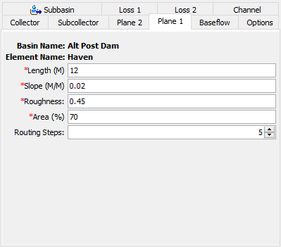
The first parameter is the length. The typical length of the conceptual plane should be entered. For impervious areas, this should be the average flow length from the point where precipitation falls, to where the runoff first enters a collection gutter or channel. For pervious areas, this should likewise be the average flow length. When using the two planes to represent pervious and impervious areas, it is helpful to adopt a convention for which plane number (one or two) represents the pervious area.
The slope is also required for each plane that will be used. The slope should represent the average slope along the flow line from the point where precipitation falls to where the runoff first enters a gutter or channel.
Roughness is the principal difference between a plane meant to represent impervious or pervious area. Roughness coefficients for natural areas are much higher than for developed areas. However, in both cases the surface roughness coefficients are higher than typical Manning's roughness coefficients used for open channel flow.
The percentage of the subbasin area occupied by each plane must be entered. If you only want to use one plane, then enter 100 for the first plane and 0 for the second. You do not need to enter length, slope, or roughness if the area will be set to zero.
The number of routing steps is used as a hint to the program when it determines the correct distance step to use during runoff calculations. Criteria based on rate of precipitation and other factors are used to automatically determine the correct distance and time steps for solving the kinematic wave equation. The default value is five.
Subcollector and Collector
A separate tab is provided for the subcollector and collector as shown in Figure 6.
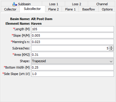
The length should be the average distance from the beginning of the subcollector to where it will enter a collector. Usually this value will be measured from maps of the stormwater collection system.
The slope should be the average slope along the average flow length. This value may be estimated from maps if they provide sufficient vertical resolution. Field survey data may be necessary to actually determine elevations of the gutter or channel. If the slope varies significantly throughout the system, this may become a determining factor in how the system is broken into subcollectors, collectors, and main channel.
The Manning's n roughness coefficient should be the average value for the whole subcollector. It is important to remember that the parameter data entered for the subcollector should be typical of all similar subcollectors in the subbasin.
The number of subreaches is used as a hint to the program when it determines the correct distance step to use during routing calculations. The default value is five.
The typical area of each subcollector must be entered. This is used to determine how to apply the composite outflow from the subcollector to the collector channel. It essentially determines the number of subcollector channels in the subbasin.
Five options are provided for specifying the cross section shape: circle, deep, rectangle, trapezoid, and triangle. The circle shape cannot be used for pressure flow or pipe networks, but is suitable for representing a free water surface inside a pipe. The deep shape should only be used for flow conditions where the flow depth is approximately equal to the flow width. Depending on the shape you choose, additional information will have to be entered to describe the size of the cross section shape. This information may include a diameter (circle) bottom width (deep, rectangle, trapezoid) or side slope (trapezoid, triangle). The side slope is dimensionless and entered as the units of horizontal distance per one unit of vertical distance.
The outflow from the subcollector enters a collector as lateral inflow. The collector channel is intended to represent small ditches or open channels that are part of an engineered stormwater management system. The parameters for the collector are exactly the same as for the subcollector.
Length, slope, Manning's n, and the number of subreaches all have the same definitions. The area served by a typical collector must be entered; this is used to apply lateral inflow from the collector to the main channel. Options for the cross section shape are exactly the same as for the subcollector.
Channel
A separate tab is provided for the channel as shown in Figure 7.
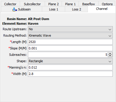
Normally it is not possible to connect upstream inflow to a subbasin element. However, because of the conceptual representation of the channel, it is possible to have an upstream inflow on the main channel. In order to connect upstream elements to the subbasin, you must select the "Route Upstream" option.
The surface runoff on the two planes is always routed using the kinematic wave method. However, you have the choice of using Muskingum-Cunge routing in the subcollector, collector, and main channel. All three channels use the same method. Select the method you wish to use.
If the route upstream option is turned on, the length should be the distance from the upstream boundary of the subbasin to the outlet. If the route upstream option is turned off, the length should be from the identifiable concentration point of the channel to the subbasin outlet. There is only one channel is each subbasin.
The slope should be the average slope for the whole channel. This value may be estimated from maps if they provide sufficient vertical resolution. Field survey data may be necessary to actually determine elevations of the channel bed for calculating the slope.
The number of subreaches is used to determine the distance step to use during routing calculations. The default value is five. This parameter is only entered when the kinematic wave routing method is selected. For natural channels that vary in cross section dimension, slope, and storage, the number of subreaches can be treated as a calibration parameter. The number of subreaches may be used to introduce numerical attenuation which can be used to better represent the movement of floodwaves through the natural system.
A cross section shape must be selected. If the kinematic wave routing method is selected, the options will include circle, deep, rectangle, trapezoid, and triangle. When the Muskingum-Cunge routing method is selected, the options will include circular, rectangle, tabular, trapezoid, triangle, and eight point. You will have to enter a Manning's n roughness value for the channel. If the tabular shape is used, you will also have to select multiple curves that describe the way in which discharge, area, and top width changes with elevation. These curves must be defined as elevation-discharge, elevation-area, and elevation-width functions, respectively, in the paired data manager before they can be used in the reach element. These curves must be monotonically increasing. Within each of the aforementioned curves, the x-axis defines the elevation while the y-axis defines the variable of interest. Elevations must be monotonically increasing. If the eight point cross section shape is used, you will also have to enter a roughness value for the left and right overbank areas. You will have to enter other appropriate parameters data based on the cross section choice.
ModClark Transform
The ModClark method is a linear, quasi-distributed transform method that is based on the Clark conceptual unit hydrograph. It fundamentally represents the subbasin as a collection of grid cells. The Clark method uses a time-area curve and the time of concentration to develop a translation hydrograph. By contrast, the ModClark method eliminates the time-area curve and instead uses a separate travel time index for each grid cell. The travel time index for each cell is scaled by the overall time of concentration. Excess precipitation falling on each grid cell is lagged by the scaled time index and then routed through a linear reservoir. The outputs from the linear reservoirs of the cells are combined to produce the final hydrograph. External utility programs are used to create the grid cell information at one of the following cell sizes: 10, 20, 50, 100, 200, 500, 1000, 2000, 5000, 10000 meters. The Component Editor is shown in Figure 8.
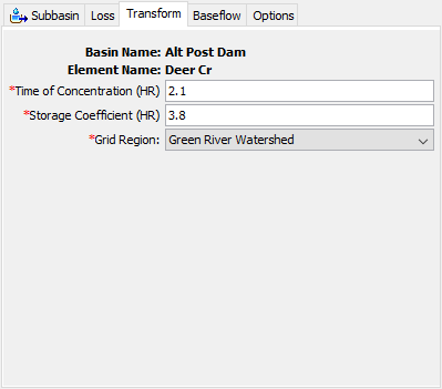
The time of concentration defines the maximum travel time in the subbasin. The grid cell in the subbasin with the largest travel time index will have exactly this specified time of concentration. All other grid cells will have a scaled time of concentration based on the ratio of the cell's travel time index to the maximum travel time index.
The storage coefficient is used in the linear reservoir for each grid cell. The same coefficient is used for all cells in the subbasin.
The grid region used by the basin model is selected on the basin model's Component Editor (see figure, Basin Model Properties). As shown in Figure 6, there is is an option to modify the grid region for individual subbasins. For now, it is not suggested that the "Grid Region" is edited for individual subbasins even though HEC-HMS version 4.4 supports multiple grid regions used within a basin model. Improved capabilities for processing precipitation data and methods for generating grid regions will be added for future version of HEC-HMS. These new capabilities will better utilize the option to select subbasin specific grid regions.
SCS Unit Hydrograph Transform
The Soil Conservation Service (SCS) unit hydrograph method defines a curvilinear unit hydrograph by first setting the percentage of the unit runoff that occurs before the peak flow (NRCS, 2007). A triangular unit hydrograph can then be fit to the curvilinear unit hydrograph so that the total time base of the unit hydrograph can be calculated. The standard unit hydrograph is defined with 37.5% of unit runoff occurring before the peak flow. This definition corresponds to a peak rate factor of 484 which incorporates the percentage of unit runoff before the peak, calculated total time base, and unit conversions when applying the equations within the US Customary unit system. An example of the Component Editor is shown in Figure 9.
The percentage of unit runoff occurring before the peak flow is not uniform across all watersheds because it depends on flow length, ground slope, and other properties of the watershed. By changing the percentage of unit runoff before the peak, alternate unit hydrographs can be computed for watersheds with varying topography and other conditions that effect runoff. The percentage of runoff occurring before the peak is reflected in the peak rate factor (PRF). It has been found that flat watersheds typically have a lower PRF that may be as small as 100. Steeper watersheds have a larger PRF thay may range up to 600. The default unit hydrograph has a PRF of 484. Unit hydrographs with specific peak rate factors are defined in the National Engineering Handbook (NRCS, 2007). A very specific case of the unit hydrograph for flat coastal watersheds is known as the Delmarva unit hydrograph (Welle, Woodward, and Moody, 1980).
The standard lag is defined as the length of time between the centroid of precipitation mass and the peak flow of the resulting hydrograph. Examination of the equations used in deriving the curvilinear unit hydrograph show that the lag time can be computed as the duration of unit precipitation divided by two, plus 60% of the time of concentration.
Snyder Unit Hydrograph Transform
The Snyder unit hydrograph is a synthetic unit hydrograph method. The original data only supported computing the peak flow as the result of a unit of precipitation. Later, equations were developed to estimate the time base of the hydrograph and the width at 50% of the peak flow. Since it does not compute all ordinates of the hydrograph, a Clark hydrograph is created in such a way that the Snyder properties are maintained.
Standard
The standard method requires the user to estimate parameters using appropriate techniques. Many approaches have been proposed for estimating the parameters, relying on different physical properties of the watershed under consideration. The approaches are typically developed by fitting the unit hydrograph parameters for a watershed with observed precipitation and discharge data. These approaches may be effective at estimating parameters in ungaged watersheds if they are similar to the watersheds used to develop the approach. The Component Editor is shown in Figure 10.
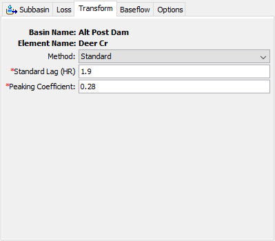
The standard lag is defined as the length of time between the centroid of precipitation mass and the peak flow of the resulting hydrograph. Many relationships for estimating lag from subbasin characteristics have been developed for different regions.
The peaking coefficient measures the steepness of the hydrograph that results from a unit of precipitation. It ranges typically from 0.4 to 0.8 with lower values associated with steep-rising hydrographs. It is estimated using the best judgement of the user, or possibly from locally-developed relationships to watershed physical features.
Ft Worth District
The Ft Worth method is the result of regional urban studies conducted by the U.S. Army Corps of Engineers, Ft. Worth District in the Dallas-Ft Worth, Austin, and San Antonio areas. The method is applicable for watersheds substantially similar to the watersheds included in the regional study. The user enters values for five physical characteristics of a subbasin. Equations from the regional study use the parameter values to calculate the Snyder standard lag. The Component Editor is shown in Figure 11.
The total length is measured from the outlet of the subbasin, along the main watercourse to the most hydraulically remote point on the subbasin boundary.
The centroid length is measured from the outlet of the subbasin, along the main watercourse, to a point opposite the subbasin centroid.
The weighted slope is the slope of the main watercourse between points located at 10 percent and 85 percent of the length of the main watercourse, measured from the subbasin outlet.
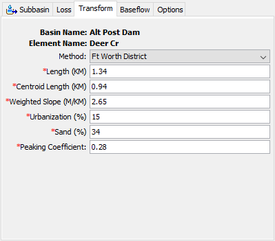
Urbanization percentage is estimated as the percentage of the subbasin where the drainage system has been improved to more efficiently carry runoff to the outlet. Such improvements may include street gutters, straightened channels, concrete lined channels, or other effeciencies. This parameter provides a way to account for the effects of urbanization on the hydrologic response of the subbasin.
The sand percentage accounts for the effect of infiltration and surface runoff properties on hydrograph generation. Zero percent indicates essentially all-clay soils with characteristically low infiltration rates. Conversely, 100 percent indicates essentially all-sandy soils with characteristically high infiltration rates.
The Fort Worth method does not include estimation of the peaking coefficient. This parameter must be estimated by another method and entered directly.
Tulsa District
The Tulsa method is the result of regional urban studies conducted by the U.S. Army Corps of Engineers, Tulsa District using watersheds across Oklahoma. The method is applicable for watersheds substantially similar to the watersheds included in the regional study. The user enters values for four physical characteristics of a subbasin. The values are used with equations developed in the regional study for estimating the standard lag and peaking coefficient. The Component Editor is shown in Figure 12.
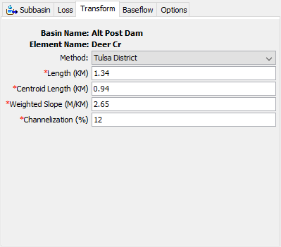
The total length is measured from the outlet of the subbasin, along the main watercourse to the most hydraulically remote point on the subbasin boundary.
The centroid length is measured from the outlet of the subbasin, along the main watercourse, to a point opposite the subbasin centroid.
The weighted slope is the slope of the main watercourse between points located at 10 percent and 85 percent of the length of the main watercourse, measured from the subbasin outlet.
Channelization percentage is estimated as the percentage of the subbasin where the drainage system has been improved to more efficiently carry runoff to the outlet. Such improvements may include street gutters, straightened channels, concrete lined channels, or other effeciencies. This parameter provides a way to account for the effects of urbanization on the hydrologic response of the subbasin.
User-Specified S-Graph Transform
The user-specified s-graph method is not synthetic. It uses a special summation unit hydrograph (abbreviated as s-graph) to represent the response of a subbasin to a unit of precipitation. The s-graph is defined with percentage of the time lag as the independent variable (x axis), and percentage of the cummulative runoff volume as the dependent variable (y axis). Computationally, the s-graph is scaled by a specified time lag and then successive differences are taken along the curve to compute a unit hydrograph directly from the scaled s-graph. A given s-graph is generally only applicable in a particular region with subbasins that share certain characteristics.
The s-graph must be chosen from a selection list of percentage curves defined previously in the paired data manager. While percentage curves are used for other applications in the program, in this case they represent percentage of unit discharge versus percentage of time lag. You will not be able to use the selection list until you create at least one s-graph. If you wish, you can use the paired data button next to the selection list to open a chooser that will assist in selecting the correct s-graph. Click on a percentage curve to view its description. Descriptions are particularly important for percentage curves because of the different applications in the program.
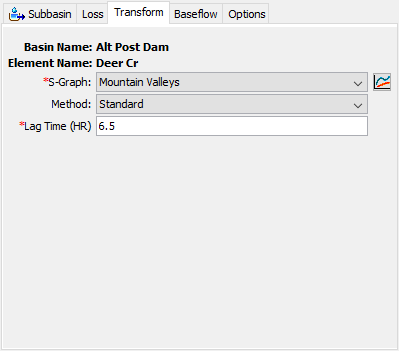
Standard
There are two different methods for specifying the lag time to be applied to the s-graph. The Standard method allows tGrhe simple specification of the lag time in hours. The lag time is defined as the length of time between the centroid of precipitation mass and the peak flow of the resulting hydrograph. An example of this method is shown in Figure 13.
Regression
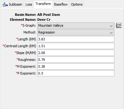
The Regression method provides for the automatic calculation of the lag time using an equation commonly applied in regional regression studies. The equation is applied to the parameters within the context of the U.S. Customary unit system. If parameters are entered in System International units, then the equation is evaluated after converting the parameters to U.S. Customary equivalents. The equation takes the following form for computing the lag time in hours:
| 3) | t_{\text {lag}}=c\left(\frac{L * L_{c a}}{S^{p}}\right)^{m} |
The length of the longest flowpath in the subbasin is specified using the L parameter. The length along the stream from the outlet to a point opposite the centroid is specified by the Lca parameter. A typical stream slope must be specified as the s parameter. The C coefficient describes hydraulic efficiency of the stream channel. The m and p parameters should be found through a regional regression study of watershed properties and observed lag time. An example of this method is shown in Figure 14.
User-Specified Unit Hydrograph Transform
The user-specified unit hydrograph method is not a synthetic technique. Consequently, a separate unit hydrograph must be developed for each subbasin. Ideally these unit hydrographs are developed from multiple storm observations when precipitation and flow have been measured at similar time intervals. The unit hydrograph developed in this manner has a so-called duration that is equal to the duration of excess precipitation. For example, a 3-hour duration unit hydrograph is generated by a precipitation event with 3 hours of excess precipitation.
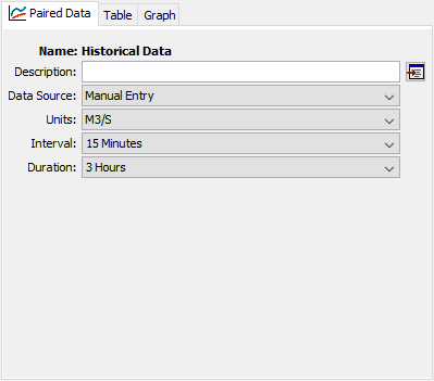
A unit hydrograph must be defined in the paired data manager before it can be used for a subbasin. An example of a unit hydrograph in the paired data manager is shown in Figure 15. Notice the duration and interval of the unit hydrograph are required. The duration must be set equal to the duration of excess precipitation used to develop the unit hydrograph. The interval is the time interval of the ordinates of the unit hydrograph. For example, a unit hydrograph developed from excess precipitation (which was uniformly distributed in space and time) over a duration of 3 hours can have a time interval of 15 minutes.
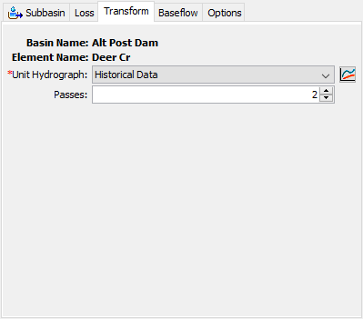
Information required for the user-specified unit hydrograph method is the selection of a unit hydrograph from the paired data manager and the number of passes, as shown in Figure 16. The unit hydograph is defined for the duration specified in the paired data manager. The number of passes is meant to correct for minor inflection points in the S-curve that is used to convert the unit hydrograph from the input duration to the duration required as per the computational interval. For instance, if the unit hydrograph 3 hour duration unit hydrograph is meant to be used within a simulation that has a computational interval of 1 hour, the unit hydrograph must be converted from a 3 hour duration to a 1 hour duration. S-curves are used to perform this conversion. If the S-curves derived from the 3 hour unit hdrograph contain inflection points, the resultant 1 hour unit hydograph may display unwanted oscillations. A maximum of 20 passes is allowed. The unit hydrograph must be entered in the paired data manager before it can be selected in the Component Editor. If you wish, you can use the paired data button next to the selection list to open a chooser to assist in selecting the correct unit hydrograph.
