Download PDF
Download page Basin Model Map.
Basin Model Map
The Basin Model Map is the primary method for visualizing the hydrologic elements that will be added to the basin model to represent the watershed. Background maps can be added to display almost any type of mapping data. It is often helpful to configure the background maps before beginning the process of creating hydrologic elements and the flow network.
Background Maps
Background maps provide a spatial context for the hydrologic elements composing a basin model. The maps are not actually used in the compute process, but they can be very helpful in showing the spatial relationship between elements. They are commonly used for showing the boundaries of a watershed or the location of streams. They can also be useful for showing supplemental information such as the location of levees. The use of background maps is always optional.
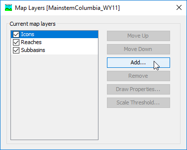
Background maps are added and removed using the Map Layers window (Figure 1). Access the window by clicking the View menu and selecting the Map Layers command. The menu command is only available if the Basin Model Map window is currently open. Any changes made to the current background maps or their draw order take affect immediately as soon as they are made.
Add a map to the list of current background maps by pressing the Add… button. A file browser opens for you to select the map file you wish to add. Select the type of map file you wish to add using the "Files of type" selection list at the bottom of the file browser.
Locate the map file you wish to add and select it. Press the Select button to add the map to the list of current background maps. If you change your mind and do not want to add a map, press the Cancel button or the X button in the upper right of the Select window. The program does not include any coordinate transformation tools so you must independently make certain that all maps you wish to use are in the same coordinate system.

Figure 1. Background maps can be added to provide a spatial context for the basin model elements. Maps can be moved up or down in the drawing order.
The current background maps are drawn in a specified order so that you can control overlapping and other drawing issues. The draw order is based on the order they are shown in the Background Maps window. The map at the bottom of the list is drawn first. After it is drawn, the map shown above it in the list is drawn second. The map shown at the top of the list is drawn last. The hydrologic elements are drawn after all of the maps have been drawn. You may temporarily turn drawing for a map "on" or "off" using the check box in the map list.
The draw order of the maps can be changed once all the desired background maps are shown in the list of current maps. To change the order of a map you must first select it in the list of current maps. Place the mouse over the desired map and click the left mouse button; the map name is highlighted to show that it is selected. Press the Move Up button to move the map up in the draw order so that other maps are drawn first. Press the Move Down button to move the map down in the draw order so that other maps are drawn after it. Each time you press the Move Up or Move Down button the map is moved one position up or down. You can press the buttons more than once to get the map to the desired position in the drawing order.
A background map can be removed from the display. Place the mouse over the map you wish to remove and select it by clicking the left mouse button; the map name is highlighted to show that it is selected. Press the Remove button. The background map is not deleted when it is removed from the list of current background maps. The files that contain the actual background map data cannot be deleted from the program; they must be deleted manually.
The drawing properties of a background map using the Shape File format can be controlled. The Draw Properties… button will be enabled whenever a map is selected that uses the Shape File format. Pressing the button will open an editor that allows control of drawing properties including colors, line style and width, shading, transparency, and other properties. Changes may be previewed before they become final. At this time, draw properties cannot be controlled for other file formats.
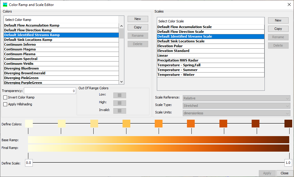
For raster data in the background, the Draw Properties... button opens the Color Ramp and Scale editor, which allows detailed customization of the way that rasters are displayed in the map. Color ramps define the color pallette used in the raster rendering. Color scales define how the values of a raster are mapped to the color pallette. A number of default color ramps and scales are provided; however, advanced controls are available to enhance the display of rasters if desired. Default color ramps and scales cannot be edited. However, if the user creates a new color ramp or scale, or copies an existing one, several options are available to the user. When the user is editing a color ramp, they can double click on any color swatch beside the "Define Colors" heading to change the color using the Select Color window. Thumbs (markers on the ramp) can be added to the ramp by right clicking on the ramps where no thumb is currently defined. Thumbs can be equally distributed the same way. Right clicking on a thumb will allow the user to select its color or remove it.

Figure 2. Background maps can be added to provide a spatial context for the basin model elements. Maps can be moved up or down in the drawing order.
Color Ramps
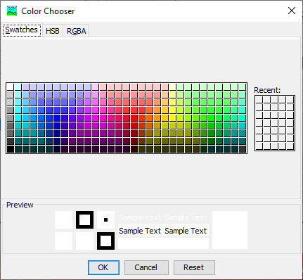
Color ramps define the sequence of colors used in mapping values in a raster. HEC-HMS provides a large number of default color ramps. The default color ramps cannot be edited, but you make a copy of a default color ramp by clicking on it and pressing the Copy button. Users may create new color ramps by selecting the New button. User-created color ramps may be renamed by using the Rename button or deleted by using the Delete button. Users may edit the color features of a user-defined color ramp: Out Of Range Colors, which define the exceptions to the color ramp (values above or below the scale, or invalid data), and the color associated with a thumb. Selecting one of the Out Of Range Color boxes, or editing the color of a thumb (by double clicking on it, or right click > Select Color...) launches the Color Chooser.

All ramps, default or user-defined, have the option to be inverted (Invert Color Ramp), for hillshading to be applied (Apply Hillshading) or to be made more transparent or opaque (Transparency, a value between 0 and 1 with 1 being completely transparent.)
Thumbs can be moved along the color scale by clicking and dragging them. They can be removed by right clicking on them and selecting Remove Thumb... Thumbs can be added by right clicking near the color ramp thumbs and selecting Add Thumb... Using the right click > Distribute Equally option will spread the thumbs out so their spacing is equal.
Color Scales
Color scales define how values in the raster are mapped to a point along the color ramp. HEC-HMS provides a number of default color scales that provide an example of how they work. There are several settings that define the behavior of a color scale:
- Scale Reference. This setting defines whether the scale values are 0 - 1 fractions of the data range (relative) or predetermined values (absolute.)
- Scale Type. This setting defines whether colors are interpolated between scale values (stretched) or a single color is used for each scale break (discrete.)
- Scale Units. This setting applies to absolute scales, and defines the units associated with the predetermined values in the scale.
Adjusting the View and Zooming
Several tools and commands are provided to zoom in, zoom out, and move around the Basin Model Map window. Several of the tools are on the toolbar. All of the commands can be found on the View menu.
There are three ways to zoom in on the Basin Model Map window. The first way is to use the scroll wheel of your mouse. When the mouse cursor is over the Basin Model Map window and the scroll wheel is rolled forward (away from you), the map will be redrawn, with the view magnified on the location where the mouse cursor was positioned while the scroll wheel was rolled. The second way to zoom in on the Basin Model Map window is to use the "shift + =" key combination on the keyboard. The third way to zoom in is to use the Zoom In command on the View menu, which will zoom in by a predefined amount. The Zoom In command is only accessible when the Basin Model Map window is open.
There are three ways to zoom out on the Basin Model Map window. The first way is to use the scroll wheel of your mouse. When the mouse cursor is over the Basin Model Map window and the scroll wheel is rolled backward (towards you), the map will be redrawn, with the view zoomed out centered on the location where the mouse cursor was positioned while the scroll wheel was rolled. The second way to zoom out on the Basin Model Map window is to use the "-" key on the keyboard. The third way to zoom out is to use the Zoom Out command on the View menu, which will zoom out by a predefined amount. The Zoom Out command is only accessible when the Basin Model Map window is open.
Navigating around the map at a constant zoom level is the default behavior for the Arrow Tool. While the Arrow Tool is activated, if the user presses down the mouse button inside the Basin Model Map window, but not on a hydrologic element, and drags the mouse in any direction, the map view will pan with the mouse drag. When the mouse button is released, the map will be redrawn. If the user clicks (presses and releases) the mouse in Arrow Tool mode on a hydrologic element, that element will be selected.
It can be very difficult to find the selected element or elements in a basin model with many hydrologic elements. A special tool has been created to zoom to the current element selection. Begin by creating an element selection. You can click on an element in the Watershed Explorer, or use the *Edit | Select By Name…* command to create a current selection. You can zoom to the selection by clicking the View menu and selecting the Zoom To Selected command. The Basin Model Map window will automatically zoom to an appropriate scale for the current element selection and center the view on the selection.
After zooming in and moving around the basin model, you may want to quickly return to viewing the entire model. You can immediately zoom to the maximum extents. Click the View menu and select the Zoom To All command. The Basin Model Map window will automatically zoom out to the coordinates specified as the maximum extents and redraw.
Drawing Elements and Labels
Hydrologic elements can be drawn as icons, as GIS features, or as GIS features and icons. Drawing with icons and GIS features is controlled separately. There is only one way to control each property. Additionally, elements can be labeled when they are drawn.
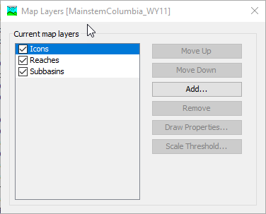
The basic method for drawing elements is with icons. Each element type has a unique icon for quick visual identification. Reach elements are an exception since they are drawn as a line from the upstream end of the reach to the downstream end. Turn the icons on and off using the View menu. Click on the View | Map Layers menu option. An "Icons" layer is located within the map layers list, as shown in Figure 3. A check is shown next to the icons layer when they are displayed in the map. You can turn off display of the icons by unchecking the icons option.
GIS features can also be turned on and off in the basin model map using the Map Layers editor. Subbasin and reach GIS features show up in the Current map layers list as Subbasins and Reaches, respectively. If no subbasin or reach GIS features have been added to the basin model, then these items, Subbasins and Reaches, will not be in the Map Layers editor. Finally, the Map Layers editor is where background map layers, shape files, can be added to the basin model map. There are additional editors available from the Map Layers editor for changing the draw properties for background map layers. Draw properties cannot be modified for Icons and subbasin/reach GIS features.

Figure 3. Turn on or off display of element icons, GIS features, and background GIS map layers from the Map Layers editor.
The advanced method for drawing subbasin, reach, and reservoir elements is with GIS features. Each subbasin element can be drawn with a polygon representing the outline of the subbasin. Each reservoir element can also be drawn with a polygon which usually represents the outline of the maximum extent of the pool. Each reach element can be drawn with a polyline representing the exact turns of the stream. GIS features must be "imported" into a basin model using the Georeference Existing Elements or the Import Georeferenced Elements options available from the GIS menu. Before adding GIS features to a basin model, the coordinate system must be defined. A basin model's coordinate system can be set using the Coordinate System option from the GIS menu.
Using GIS features is optional. When GIS features are used, it is not necessary to have subbasin, reservoir, and reach geometric data. It is permissible to use GIS features for one, two, or all three types of elements. Additionally, it is not necessary to have GIS features for every single subbasin, reservoir, or reach in the basin model. GIS features will be drawn for the elements for which it is available.
Element labels can be drawn with element icons or GIS features. Currently, the only option for the label is the name of the element. Turn the element labels on and off using the View menu. Click on the View menu and select the Draw Element Labels command to choose how to draw the labels. A check is shown next to the selected option. To change the selected option, use the mouse to click on a different choice.
Displaying Flow Directions
Each reach element in the network only allows flow to move in one direction; from upstream to downstream. If a reach is connected to its upstream and downstream elements in the wrong direction, then the network may not be a good representation of the physical watershed. You can verify the flow directions by displaying direction arrows. When the direction arrows are turned on, arrow heads are added to reach elements to show the flow direction. There is only one way to turn the flow direction arrows on and off.
Turn the flow direction arrows on and off using the View menu. Click on the View menu and select the Draw Flow Directions command. A check is shown next to the menu command to indicate that the arrows are turned on. You can turn off the direction arrows by clicking on the same menu command again.