Download PDF
Download page Hydrologic Elements.
Hydrologic Elements
Hydrologic elements are the basic building blocks of a basin model. An element represents a physical process such as a watershed catchment, stream reach, or confluence. Each element represents part of the total response of the watershed to atmospheric forcing. Seven different element types have been included in the program: subbasin, reach, reservoir, junction, diversion, source, and sink.
An element uses one or more mathematical models to describe a physical process occurring in the watershed. Sometimes the model is only a good approximation of the original physical process over a limited range of environmental conditions. Data availability and the required parameters of a model can also determine fitness. To make the program suitable for many different conditions, most elements have more than one model or method for approximating the physical process. For example, there are seven different methods for specifying overland flow for a subbasin.
Creating a New Element
New hydrologic elements are created directly in the Basin Model Map window. Begin the process of creating a new element by opening the basin model into which you wish to add a new element. Select a basin model in the Watershed Explorer to open it. Separate tools are provided in the toolbar for each of the seven different kinds of element. Select the tool corresponding to the type of element you wish to create: subbasin, reach, reservoir, junction, source, diversion, or sink. After selecting the appropriate tool, move the mouse over the Basin Model Map window; the mouse cursor changes to cross hairs. Move the mouse until the cross hairs are over the location where you wish to create the element. Click the left mouse button. A window will open where you can name and describe the new hydrologic element that will be created, as shown in Figure 1. A default name is provided for the new element; you can use the default or replace it with your own choice. A description can also be entered. If the description is long, you can press the button to the right of the description field to open an editor. The editor makes it easier to enter and edit long descriptions. When you are satisfied with the name and description, press the Create button to finish the process of creating the new hydrologic element. You cannot press the Create button if no name is specified for the new element. If you change your mind and do not want to create a new hydrologic element, press the Cancel button or the X button in the upper right to return to the Basin Model Map window. After you finish creating one element, the element creation tool is still selected and you can create additional new elements of the same type.
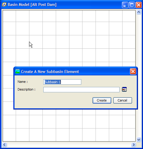
Figure 1. Creating a subbasin in a new basin model. The subbasin tool was selected on the toolbar. The cursor changed from cross hairs back to a pointer when the left mouse button was pressed at the desired location for the new element. It is a good idea to customize the default name.
Most of the elements are created by clicking the mouse button over the location where you want to create the element. However, two mouse clicks are required when creating a reach element. To create a reach, begin by selecting the correct tool from the toolbar. Next click once over the location you want to be the upstream end of the reach. Then as you move the mouse you will see a line connecting the mouse to the upstream end of the reach. Move the mouse to the location you want to be the downstream end of the reach and click. You will finish the process of creating a reach by selecting a name and entering the optional description.
Copying an Element
Hydrologic elements can be copied to the clipboard from one basin model and then exact duplicates can be pasted in either the same or a different basin model. Begin by opening the basin model that contains the element or elements you wish to copy. Select the hydrologic element you wish to copy by clicking on it with the arrow tool. You may also select more than one element in the map by either holding down the control or shift keys to select multiple elements, or by drawing a box around multiple elements. The selected element or elements become highlighted after the selection. After you make a selection, go to the Edit menu and select the Copy button as shown in Figure 2. You can now paste the selection into the same or a different basin model. The copy command is only available if there is at least one element selected.
A single element can be copied using the right mouse context menu. Select an element in the basin model map, then place the mouse on top of the selected element and click the right mouse button. A context menu will open with Copy Element menu option.
As shown in Figure 2, menu options are available from the Edit menu to select all elements upstream of the selected location or to invert the selected elements. The program tracks the hydrologic connectivity of all elements within a basin model. The Edit | Select Upstream menu option was added as a quick option for selecting multiple elements upstream of a selected junction, reach, reservoir, or division element. The Edit | Invert Selection menu option was added as a quick option of inverting the selected set of basin model elements.
The invert selection option could be used to select all elements downstream of a location. First, you would choose a location in the basin model map, and then choose the select upstream option to select all points upstream of the selected location. Second, you would choose the invert selection option to switch the selection, effectively selecting all elements downstream of the originally selected element.
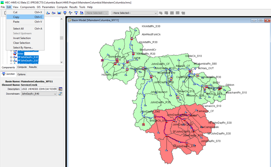
Figure 2. Copying a group of selected elements from the basin map to the clipboard; the elements will remain in the basin model. If the elements were cut, they would be on the clipboard but removed from the basin model.
Pasting an Element
An element in the clipboard can be pasted into a basin model. Pasting an element does not remove it from the clipboard so you can paste the same selection into multiple basin models. Begin by opening the basin model into which you wish to paste elements from the clipboard. Select the arrow tool and move the mouse to the location where you wish to paste the element. If there are multiple elements on the clipboard then you should place the mouse where you want the center of the element grouping to be located. Press the right mouse button as shown in Figure 3. A context menu is displayed that contains several choices including paste. Click the Paste Element command. The paste command is only available if there is at least one element on the clipboard.
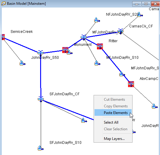
Figure 3. Pasting an element selection into the basin map. The mouse was placed where the pasted element should be added to the basin map and the right mouse button was pressed. Now the Paste Element command can be selected.
Cutting an Element
An element can be cut from a basin model and removed to the clipboard. Cutting an element places an exact but independent copy of the element on the clipboard and then deletes it from the basin model. Once an element is in the clipboard it can be pasted into the same basin model from which it was copied or it can be pasted into a different model. Begin by opening the basin model from which you wish to cut an element. Select the hydrologic element you wish to cut by clicking on it with the arrow tool. You may also select more than one element in the map. The selected element or elements become highlighted after the selection. After you make a selection, place the mouse over a selected element and press the right mouse button. A context menu is displayed that contains several choices including cut. Click the Cut Element command. If more than one element is selected in the basin model map, then the Cut menu option from the Edit menu must be used. You can now paste the selection into the same or a different basin model. The cut command is only available if there is at least one element selected.
Renaming an Element
Rename a hydrologic element using the "Components" tab of the Watershed Explorer. Select the element you wish to rename by clicking on it in the Watershed Explorer; it will become highlighted. Keep the mouse over the selected element and click the left mouse button again. The highlighted name will change to editing mode as shown in Figure 4. You can then move the cursor with the arrow keys on the keyboard or by clicking with the mouse. You can also use the mouse to select some or all of the name. Change the name by typing with the keyboard. When you have finished changing the name, press the Enter key to finalize your choice. You can also finalize your choice by clicking elsewhere on the "Components" tab. If you change your mind while in editing mode and do not want to rename the selected hydrologic element, press the Escape key.
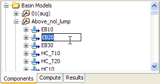
Figure 4. Renaming an element in the Watershed Explorer. You can right-click on an element and select the Rename… command. Alternately, click with the left mouse button on an element that is already selected to immediately enter editing mode and change the name.
Deleting an Element
There are three ways to delete a hydrologic element. All methods for deleting an element remove it from the basin model. Once an element has been deleted it cannot be retrieved or undeleted.
The first way to perform a deletion is from the Basin Model Map window. Select the hydrologic element you wish to delete by clicking on it with the arrow tool. The selected element becomes highlighted after the selection. After you make a selection, place the mouse over a selected element and press the right mouse button (Figure 5). A context menu is displayed that contains several choices including Delete Element. Click the Delete Element command. A window will open where you must confirm that you wish to delete the selected hydrologic element. Press the OK button to delete the element or elements. If you change your mind and do not want to delete the element selection, press the Cancel button or the X button in the upper right to return to the Basin Model Map window.
The second way to delete an element also uses the selection in the map. Select one or more elements that you wish to delete. Press the Delete key on the keyboard. You will have to confirm your choice to delete.
The third way to delete is from the "Components" tab of the Watershed Explorer. Move the mouse over the element you wish to delete and press the right mouse button as shown in Figure 6. A context menu is displayed that contains several choices including delete. Click the Delete command. You will have to confirm your choice to delete.
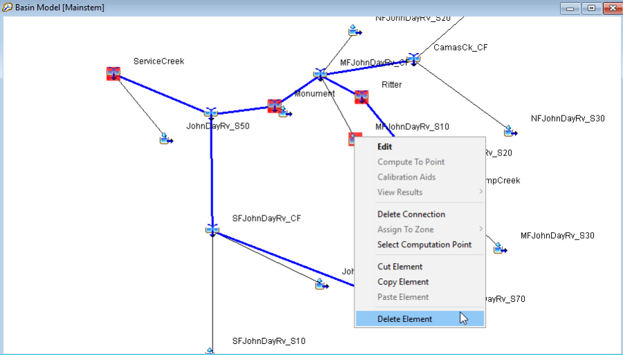
Figure 5. Deleting a single element from the basin map.
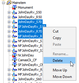
Figure 6. Deleting elements from the Watershed Explorer.
Optional Element Properties
Several optional features are available at every hydrologic element regardless of the type of element. While some of the features may be required for certain capabilities such as parameter estimation with optimization, they are all optional for normal use in simulation runs. All optional features are contained in a Component Editor that is automatically displayed along with the main element editor. Select an element in the Watershed Explorer or the basin map to view its Component Editor (Figure 7).
A time-series discharge gage can be specified as observed flow for any hydrologic element. When used with subbasins, the gage should generally represent the measured flow at the outlet of the subbasin. For reaches, the gage should represent the measured flow at the downstream end of the reach. For all other elements it should be a measured estimate of the outflow from that element. The observed flow is added to the time-series results for the element and appears in summary tables, time-series tables, and graphs.
A time-series stage gage can be specified as observed stage for any hydrologic element. When used with subbasins, the gage should generally represent the measured stage at the outlet of the subbasin. For reaches the gage should represent the measured stage at the downstream end of the reach. For all other elements it should be a measured estimate of the stage at that element. The observed stage is added to the time-series results for the element. It is best used in combination with the elevation-discharge curve described next.
A gage for observed snow water equivalent (SWE) can be added to subbasins. This can be helpful when calibrating simulations that include modeling the accumulation and melting of a snowpack. The observed data can represent either measurements at a point, or may be the result of external averaging calculations for the whole subbasin. Observed SWE is only available for subbasin elements.
A gage for observed pool elevation can be added to reservoirs. This can be helpful when calibrating simulations. Using this data can be nearly equivalent to having observed inflow to the reservoir. Even when observed inflow in available, the observed flow for an element should be compared to the computed outflow. Observed pool elevation is only available for reservoir elements.
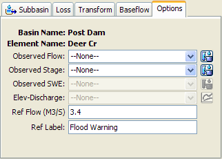
Figure 7. Element component editor for specifying option properties.
The program fundamentally computes flow for each of the hydrologic elements included in a basin model. An elevation-discharge curve can be specified so that stage can be computed as well. If a curve is specified, the stage for each time step is determined by taking the computed flow and using it to interpolate elevation from the curve. The computed stage is added to time-series results for the element and appears in summary tables, time-series tables, and graphs.
The flow ratio is only shown for subbasin and source elements, and only if the basin model is set to allow flow ratios. To enable or disable flow ratios, access the Component Editor for the basin model and make the desired selection. When the ratios are enabled in the basin model, the flow ratio can be entered for subbasin and source elements. The ratio is applied to the computed flow from the subbasin or source in order to compute the final outflow.
A reference flow can be specified to assist in interpreting computed flow results. The flow is added to the element results graph as a horizontal marker line at the specified flow value. The marker line is labeled with the specified label. The reference flow can represent any significant flow value such as bank-full discharge, flood watch, levee overtopping, or observed high water mark for a storm event.
Element Inventory
The element inventory provides a listing of some or all of the hydrologic elements in a basin model. This is helpful for reviewing the various element names and descriptions. To access the inventory, click the Parameters menu and select the Element Inventory command. A sample inventory is shown in Figure 8. If there is a current element selection, only the selected elements will be shown in the inventory when the window opens; you can switch to showing all elements by using the selection control at the top of the window. All hydrologic elements in the basin model will be shown if no elements are currently selected.
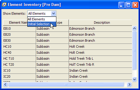
Figure 8. Typical element inventory for a basin model. You can switch between viewing the initial element selection from the basin map, or all elements.
Finding and Selecting Elements
The simplest way to find a hydrologic element in a basin model is to select it in the Watershed Explorer. All of the elements in a basin model are shown in hydrologic order under the basin model icon. Click on an element icon in the Watershed Explorer and it will become selected. The selected element is highlighted in the Watershed Explorer and in the Basin Model Map window. More than one element may be selected at a time but only the Component Editor for the first selected element is shown.
You can also find and select a hydrologic element in the Basin Model Map window. Begin by making sure the Arrow Tool is selected on the toolbar. Examine the element icons in the Basin Model Map window until you find the one you wish to select. Click on it with the arrow cursor and it will become selected. The selected element is highlighted in the Basin Model Map window and in the Watershed Explorer. After you make the first selection, you can add to the selection by holding the shift key and clicking on additional elements. You can select several elements simultaneously by using the arrow cursor to drag a box around the desired elements. To select using a drag box, move the mouse to a blank area of the map. Hold the left mouse button and drag the mouse. A box is drawn to show which elements will be selected when you release the mouse button.
It can be difficult to find a specific hydrologic element in a large basin model with many elements. A special tool is included that can be used to help locate a single element or a group of elements. Access the tool by clicking the Edit menu and selecting the Select By Name… command (Figure 9). The Select By Name window will remain open until it is closed by pressing the Close button or the X button at the upper corner of the window. Elements are selected in the basin model according to the selections on the Select Special window every time the Apply button is pressed. There are three components to a special selection.
The first component of a special selection is the element name. You may enter a specific name, for example, the name of an element appearing in an error message. You can find all elements that begin with a specific sequence of letters by entering those letters followed by an asterisk. For example, entering sub* will find all elements with names that start with "sub". You can also find all elements that end with a specific sequence of letters by entering an asterisk followed by those letters. For example, entering *creek will find all elements with names that end in "creek". Finally you can find all elements that contain a specific sequence of letters by entering an asterisk, the letters, and ending with another asterisk. For example, entering *basin* will find all elements with names that contain "basin". By default the "Element Name" is set to an asterisk so that the special selection will find all element names.
The second component of a special selection takes the result of limiting by element name and further limits it based on the element type. Elements will only be selected if they match the name criteria and their type is checked on. For example, to only search among the source elements, check off all element types except source. You may check on one, several, or all element types. The default is to search among all element types.
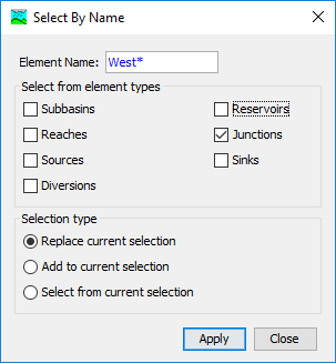
Figure 9. Using the special selection tool to select all junctions whose names begins with the letters "West".
The third component of a special selection is the selection type to create. You may replace the current selection. This means that whatever elements are found to meet the name criteria and the element type criteria will become the selected elements. Any previously selected elements will no longer be selected. You may alternately add to the current selection. This means the new selection will include any elements that are currently selected plus the elements that meet the new name and element type criteria. Finally, you can select from the current selection. In this case the name and element type criteria are further limited by only selecting from among the elements that are already selected.