Download PDF
Download page Control Specifications.
Control Specifications
Control specifications are one of the main components in a project, even though they do not contain much parameter data. Their principle purpose is to control when simulations start and stop, and what time interval is used in the simulation.
Creating a New Control Specifications
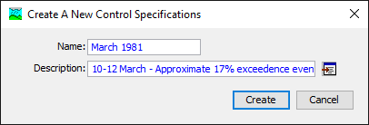
A new control specifications is created using the Control Specifications Manager. To access the manager, click on the Components menu and select the Control Specifications Manager command. The manager will open and show all of the control specifications currently in the project. The manager can remain open while you manage control specifications or while you perform tasks elsewhere in the program. You can close the manager using the X button in the upper right corner. The buttons to the right of the specifications list can be used to manage existing specifications or create a new one. To create a new control specifications, press the New… button. After you press the button a window (Figure 1) will open where you can name and describe the new control specifications that will be created. A default name is provided for the new specifications; you can use the default or replace it with your own choice. A description can also be entered. If the description is long, you can press the button to the right of the description field to open an editor. The editor makes it easy to enter and edit long descriptions. When you are satisfied with the name and description, press the Create button to finish the process of creating the new control specifications. You cannot press the Create button if no name is specified for the new specifications. If you change your mind and do not want to create a new control specifications, press the Cancel button or the X button in the upper right to return to the Control Specifications Manager window.
Copying a Control Specifications
There are two ways to copy a control specifications. Both methods for copying a specifications create an exact duplicate with a different name. Once the copy has been made it is independent of the original and they do not interact.
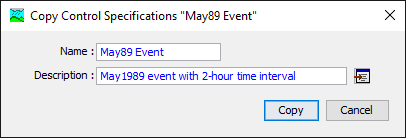
The first way to create a copy is to use the Control Specifications Manager, which is accessed from the Components menu. Select the control specifications you wish to copy by clicking on it in the list of current control specifications. The selected specifications is highlighted after you select it. After you select a specifications you can press the Copy… button on the right side of the window. A new Copy Control Specifications window (Figure 2) will open where you can name and describe the copy that will be created. A default name is provided for the copy; you can use the default or replace it with your own choice. A description can also be entered; if it is long you can use the button to the right of the description field to open an editor. When you are satisfied with the name and description, press the Copy button to finish the process of copying the selected control specifications. You cannot press the Copy button if no name is specified. If you change your mind and do not want to copy the selected control specifications, press the Cancel button or the X button in the upper right to return to the Control Specifications Manager window.
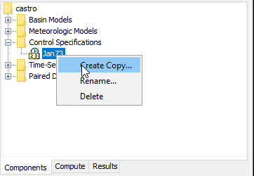
The second way to copy is from the "Components" tab of the Watershed Explorer. Move the mouse over the control specifications you wish to copy, then press the right mouse button (Figure 3). A context menu is displayed that contains several choices including copy. Click the Create Copy…command. A new Copy Control Specifications window will open where you can name and describe the copy that will be created. A default name is provided for the copy; you can use the default or replace it with your own choice. A description can also be entered; if it is long you can use the button to the right of the description field to open an editor. When you are satisfied with the name and description, press the Copy button to finish the process of copying the selected control specifications. You cannot press the Copy button if no name is specified. If you change your mind and do not want to copy the selected control specifications, press the Cancel button or the X button in the upper right of the Copy Control Specifications window to return to the Watershed Explorer.
Renaming a Control Specifications
There are two ways to rename a control specifications. Both methods for renaming a specifications change its name and then all references to the old specifications name are automatically updated to the new name.
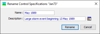
The first way to perform a rename is to use the Control Specifications Manager, which you can access from the Components menu. Select the control specifications you wish to rename by clicking on it in the list of current control specifications. The selected specifications is highlighted after you select it. After you select a specifications you can press the Rename… button on the right side of the window. A new Rename Control Specifications window (Figure 4) will open where you can provide the new name. If you wish you can also change the description at the same time. If the new description will be long, you can use the button to the right of the description field to open an editor. When you are satisfied with the name and description, press the Rename button to finish the process of renaming the selected control specifications. You cannot press the Rename button if no name is specified. If you change your mind and do not want to rename the selected control specifications, press the Cancel button or the X button in the upper right of the Rename Control Specifications window to return to the Control Specifications Manager window.
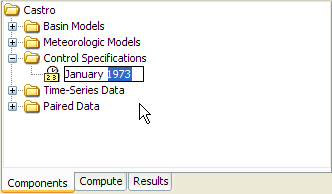
The second way to rename is from the "Components" tab of the Watershed Explorer. Select the control specifications you wish to rename by clicking on it in the Watershed Explorer; it will become highlighted. Keep the mouse over the selected specifications and click the right mouse button. Select the Rename… command from the menu and the highlighted name will change to editing mode as shown in Figure 5. You can then move the cursor with the arrow keys on the keyboard or by clicking with the mouse. You can also use the mouse to select some or all of the name. Change the name by typing with the keyboard. When you have finished changing the name, press the Enter key to finalize your choice. You can also finalize your choice by clicking elsewhere on the "Components" tab. If you change your mind while in editing mode and do not want to rename the selected control specifications, press the Escape key.
Deleting a Control Specifications
There are two ways to delete a control specifications. Both methods for deleting a specifications remove it from the project and then automatically update all references to that specifications. Once a specifications has been deleted it cannot be retrieved or undeleted. Any references to the deleted specifications will switch to using no control specifications, which is usually not a valid choice during a simulation. At a later time you will have to go to those components and manually select a different control specifications.
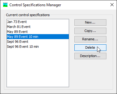
The first way to perform a deletion is to use the Control Specifications Manager, which you can access from the Components menu. Select the control specifications you wish to delete by clicking on it in the list of current control specifications. The selected specifications is highlighted after you select it. After you select a specifications you can press the Delete button on the right side of the window. A window will open where you must confirm that you wish to delete the selected specifications as shown in Figure 6. Press the OK button to delete the specifications. If you change your mind and do not want to delete the selected control specifications, press the Cancel button or the X button in the upper right to return to the Control Specifications Manager window.
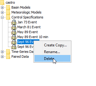
The second way to delete is from the "Components" tab of the Watershed Explorer. Select the control specifications you wish to delete by clicking on it in the Watershed Explorer; it will become highlighted. Keep the mouse over the selected specifications and click the right mouse button (Figure 7). A context menu is displayed that contains several choices including delete. Click the Delete command. A window will open where you must confirm that you wish to delete the selected specifications. Press the OK button to delete the specifications. If you change your mind and do not want to delete the selected control specifications, press the Cancel button or the X button in the upper right to return to the Watershed Explorer.
Time Window
Each control specifications sets the time window over which a simulation will be performed. The window is specified using a separate start date, start time, end date, and end time. There is no limit on the length of a time window, or the number of simulation time steps it can contain. The program contains simulation methods suitable for both event and continuous simulation. Whether a particular simulation is considered event or continuous depends on the length of the time window set in the control specifications and the methods chosen in the basin model.
The program is capable of processing dates from 1583 AD through 4000 AD. All dates are processed according to the rules specified in the Gregorian calendar for leap year. The format for specifying a date is to use two digits for the day, followed by the three-letter month abbreviation, and finally the four digit year. Two digit years are never used for entering or displaying dates. For example, the date February 8, 1936 should be entered as follows:
08Feb1936
It is very important to use the correct format or the date you enter may be incorrectly interpreted. If the program is not able to interpret a date, the entry field will become blank. The same format is used for both start and end dates, and for dates throughout the program.
The program processes times assuming an arbitrary local time zone that does not observe summer time (daylight savings in the United States). It uses 24-hour clock time instead of AM or PM notation. Time windows can only be entered with minute resolution. Times may range from 00:00 at the beginning of a day to 23:59 at the end. If a time of 24:00 is entered, it is automatically converted to 00:00 on the following day. For example, the time of 2:15:00 PM should be entered as follows:
14:15
It is very important to use the correct format, including the colon, or the time may be incorrectly interpreted. The same format is used for start and end times, and for times throughout the program.
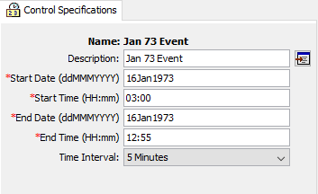
Enter or edit the time window in the Component Editor for the control specifications. Access the editor from the Watershed Explorer on the "Components" tab by clicking on the desired control specifications icon (Figure 8). Type the date and time information in the appropriate fields.
Time Interval
Each control specifications includes the time interval that will be used to perform computations during a simulation. The same interval will be used when viewing time-series results from the simulation. In some cases, computations may be carried out at a shorter time interval and results interpolated to the interval specified in the control specifications. Some methods in the basin model have parameters that are sensitive to time interval. Those parameters should be estimated with knowledge of the time interval in the control specifications.
Time-series gage data and grid data are interpolated to the time interval during a simulation. The original data stored for the gage or grid is not altered; the available data is interpolated as part of the simulation process and is not retained. The interpolation is performed linearly in time between the available data points.
Specify the time interval in the Component Editor for the control specifications (Figure 8). Access the editor from the Watershed Explorer on the Components tab by clicking on the desired control specifications icon. Select the desired time interval from the list of available choices. The possible choices range from 1 minute to 1 day.
It is important that any minutes included in a start or end time be an integer multiple of the time interval. For example, if the time interval were chosen to be 10 minutes, then the start or end time could be 10:00, 10:10, 10:20 or other multiples of 10 minutes. For the same time interval of 10 minutes, the start or end time could not be 10:07 because that is not an integer multiple of the time interval.
Gridded Data Output Interval
All of the general time-series results computed during a simulation use the time interval specified in the Control Specifications. The time interval also controls the solution of the equations that produce the values seen in the time-series results. In general the equations and the results are linked by using the same time interval as specified in the Control Specifications.
Some of the methods available in the subbasin element are gridded, and consequently calculate results for each grid cell within a subbasin. A number of time-series results are available for these methods. The values in each time-series represent an area-weighted average of all the grid cells in the subbasin. That is, the value shown for a particular time interval is the area-weighted average over all the grid cells in the subbasin during that time interval. These results are valuable for showing the general trends over the whole subbasin.
Some of the gridded simulation methods are also capable of storing gridded results. These gridded results represent the basis of the area-weighted averages produced in the time-series results. The gridded results are valuable for showing the heterogeneous processes occurring across the subbasin. However, gridded results require more memory space to store than do time-series results. Storing all of the gridded results for all methods that produce gridded results significantly increases the size of the simulation output files.
Gridded output results are only stored when specifically requested in the program settings which are described in Program Settings. The Program Settings include an option on the "Results" tab to store the gridded state variable results. Activating this option will make the gridded results from the simulation components available. Activating the output option also adds the gridded data output interval to the Component Editor. The gridded data output option will not be visible unless gridded state variables will be output.
The gridded state variables will be stored at the gridded data output interval. However, the internal calculations will be performed at the time interval, and the time-series results will use the time interval. For example, a time interval of 1 hour might be specified for a continuous simulation that spans several months. A gridded data output interval of 1 day could be selected in order to look at the gridded results at the end of each day.
Grid Time Shift
All simulations are completed assuming an arbitrary local time zone. All input data are assumed to be in the local time zone and simulation results are stored assuming the local time zone. However, gridded precipitation data is typically published with a time zone of GMT. The gridded precipitation method includes an option to shift the data to the local time zone so that it may be aligned with other input data during the simulation. The gridded output results are normally stored in the local time zone. By using the grid time shift, the gridded output results are shifted after the simulation is complete so that the gridded output will align with the original gridded precipitation data.
This feature is considered an interim solution to processing input data with different time zone definitions. Eventually, a complete solution will be implemented where all time-series and gridded input data are labeled with a time zone and the output time-series and gridded simulation results will also be labeled with a time zone.