Download PDF
Download page Adjusting Parameters for the Forecast.
Adjusting Parameters for the Forecast
The subbasins and reaches in a Forecast Alternative are initialized to default values using the parameter values from the Basin Model. The parameter values in the elements may be adjusted for the forecast without altering the original parameter values in the Basin Model. Note that it is not required to make parameter adjustments during a forecast. When no parameter adjustments are made, the values taken from the Basin Model are used without modification for the forecast. However, most forecasts will include parameter adjustments to reflect current conditions in the watershed due to antecedent and meteorologic conditions.
Zone Parameter Adjustments
Adjustments are entered using the parameter editors for the Forecast Alternative. The editors are accessed on the Compute menu by using the Forecast Parameter Tables command. Be sure to select a current Forecast Alternative in order to access the editors. A separate parameter editor is shown for each loss rate, transform, baseflow, and routing method used in the Basin Model. Adjustments are set for each zone using the upper half of the parameter editor, as shown in the following figure. The upper half of of the editor includes one row for each zone. Without zone adjustments, element results are calculated purely from the Basin Model parameters.
Two columns are included for each editable parameter in the loss rate, transform, baseflow, routing, or snow method. The first column labeled Zone Average shows the area-weighted average default parameter value computed over all elements in the zone. A parameter adjustment can be entered in the second column labeled Adjustment. If the adjustment is left blank, then the default parameter value will be used for each element. You may add a fixed value to the parameter in all elements within the zone. For example, entering an adjustment of +0.2 would increase the parameter value by 0.2 at each element in the zone. You may subtract a fixed value from the parameter in all elements within the zone. For example, entering -2.1 would decrease the parameter value by 2.1 at each element in the zone. You may multiply the parameter at each element within the zone by a fixed value. For example, entering an adjustment of *0.8 would multiple the parameter value by 0.8 at each element in the zone. Finally, you may replace the default parameter value at each element within the zone by a fixed value. For example, entering an adjustment of 7.0 would set the parameter value to 7.0 at each element in the zone. Press the Apply button when you have finished entering zone parameter adjustments.
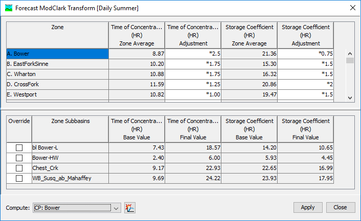
The bottom half of the parameter editor shows details about the parameter values for the elements in the selected zone. Clicking on a row in the upper half of the parameter editor selects a zone. The lower half of the editor will show one row for each element in the selected zone. Two columns are shown for each parameter in the loss rate, transform, baseflow, or routing method. The first column labeled Base Value shows the default parameter value taken from the Basin Model. The second column labeled Final Value shows the adjusted parameter value that will be used during the forecast. Adjusted parameter values are calculated using any zone adjustments entered in the upper half of the editor. The adjusted parameter values are updated every time the Apply button is pressed. Finally, users can select a computation point and all hydrologic elements upstream can be computed from this editor.
Element Parameter Overrides
Zone Parameter Adjustments provide a quick method for changing subbasin and reach parameters to produce a forecast. However, sometimes one or more elements within a zone need a different adjustment than the rest of the elements in that same zone. An Element Override may optionally be specified to use different parameter values at an individual subbasin or reach within a zone. Without element overrides, element results are calculated purely from the Basin Model parameters and zone adjustments.
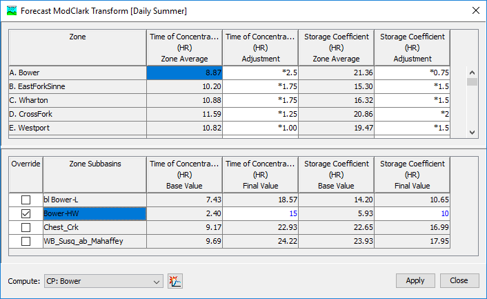
To begin, you must Enable the Override for the desired element, as shown in the following figure. Within the upper half of the parameter editor, click on the row for the Zone where the element is located. That zone will become the current zone and the elements within the zone will be shown in the lower half of the parameter editor. Next, click on the Override checkbox located in the lower half of the editor next to the element name. Once the override is enabled, the Final Value column for each parameter will be editable for the selected element. The default final value for each parameter is computed automatically by applying the zone adjustment, if any, to the default value found in the Basin Model. During an override operation, the final value of a parameter can be changed. You may choose to override only one parameter in the loss rate, transform, baseflow, or routing method. Alternately, you may choose to override several parameters or all parameters. Any override adjustments are removed when the checkbox for the element is cleared.
Slider Adjustments
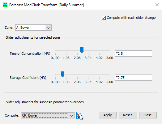
A Slider Adjustment is an alternate way to view and change a Zone Parameter Adjustment or an Element Parameter Override. An example of a slider adjustment is shown in the following figure. Instead of typing a new value for the adjustment in a data entry table, the slider can be moved with the mouse to quickly obtain a new factor. Slider adjustments enhance existing zone parameter adjustments and element parameter overrides. Configuration information is required for each adjustment or override that will be manipulated with a slider. Preparing to use a slider adjustment begins with selecting the adjustments or override and entering configuration information.
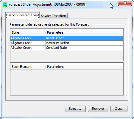
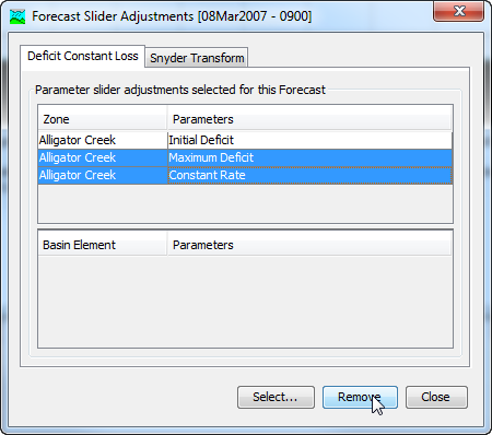
Slider Adjustments are part of the parameter data for a Forecast Alternative. They can be selected or removed without affecting the zone parameter adjustments or element parameter overrides. The sliders for the current Forecast Alternative are accessed on the Compute menu by using the Forecast Slider Adjustments command. The forecast slider adjustments manager opens and shows a separate tab for each loss rate, transform, baseflow, and routing method in the Basin Model used for the Forecast Alternative (illustrated in the figure below). The upper table on the tab shows all of the zone parameter adjustments that have been selected for a slider adjustment. Each adjustment that has been selected is shown on a separate row. Parameters from multiple zones will all be shown in the table. The lower table shows all of the element parameter overrides that have been selected for a slider adjustment. Each override has a separate row and multiple elements in multiple zones are all shown together. The tables will be empty if no adjustments or overrides have been selected for slider adjustments.
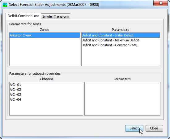
Select Slider Adjustments by clicking the Select button. A window will open where zone parameter adjustments and element parameter overrides can be selected (shown in the following figure). A separate tab is included for each loss rate, transform, baseflow, and routing method in the Basin Model used for the Forecast Alternative.
Zone Parameter Adjustments are selected in the upper half of the screen. Clicking on a Zone Name will display all of the parameter adjustments that are available for selection. There are multiple ways to select an adjustment. You may click on a parameter adjustment and press the Select button. Alternately you may double click on a parameter adjustment and it will be selected. To select multiple adjustments simultaneously, hold the control key and click on each parameter adjustment. The selected adjustments are highlighted. Press the Select button to choose all of the selected adjustments. Press the Close button when you have finished selecting zone parameter adjustments.
Element Parameter Overrides are selected in the bottom half of the screen. Elements are only shown in the bottom half if they are in the zone currently selected in the upper half. Click on a Zone Name in the upper half to select it; the selected zone will remain highlighted until a different zone is selected. Move to the bottom half and select an element by clicking on it. The available element parameter overrides will be shown after an element is selected. Overrides are selected in the same way as zone parameter adjustments by pressing the Select button or by double clicking on an override. Press the Close button when you have finished selecting element override adjustments.
Slider Adjustments can be removed from the Forecast Alternative using the Select Forecast Slider Adjustments Manager (shown in the following figure). Access the manager for the current Forecast Alternative by selecting the Compute menu and clicking the Forecast Slider Adjustments command. Remove a slider for a zone parameter adjustment by clicking on the adjustment. The adjustment is highlighted when it is selected. Press the Remove button and the slider will be removed from the slider adjustments. Slider adjustments for element overrides can be removed the same way. Multiple slider adjustments can be removed simultaneously by holding the control key and clicking on each of the adjustments before pressing the Remove button.
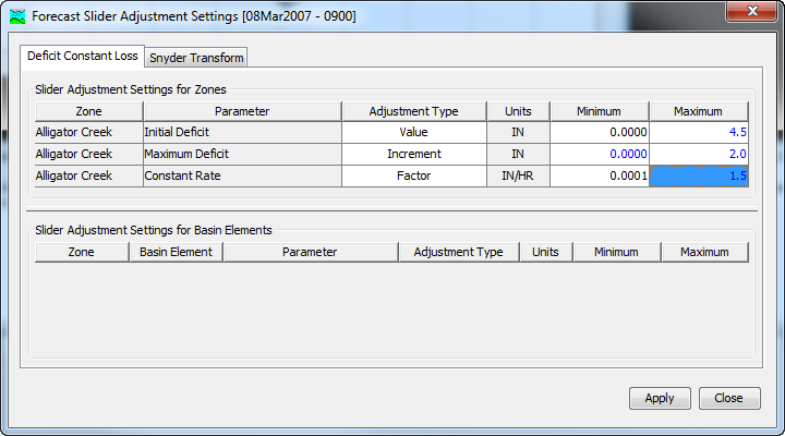
Selecting Slider Adjustments is the first step in preparing them for use. Each slider adjustment must also be configured with the properties necessary to operate properly in the Slider Editor. Access the settings for the current Forecast Alternative by selecting the Compute menu and clicking the Forecast Slider Settings command. The table in the upper half shows the slider adjustments for zone parameters (shown in the following figure). The first column displays the Zone Name while the second column shows the Parameter Name. The next column shows the selected Adjustment Type. The type may be a value, increment, or factor. The units of each zone parameter are shown for reference. The minimum value sets the left side of the slider range while the maximum sets the right side of the range. The minimum and maximum values should be specified carefully giving consideration to the nature of each parameter.
The table in the lower half shows the Slider Adjustments for Element Parameter Overrides. The Zone Name, Element Name, and Parameter Name is shown for each slider adjustment. Use the same approach for entering the settings for element parameter overrides as for zone parameters. The slider adjustment settings can be closed when all configurations are complete.
The Slider Adjustments can be opened from the Forecast Parameter Adjustment Editors. The editors are accessed on the Compute menu by using the Forecast Parameter Adjustments command. Pressing the Slider Adjustments button will open the Slider Editor. The button can only be pressed after the settings have been configured in the Forecast Slider Settings.