Download PDF
Download page Selecting a Loss-Gain Method.
Selecting a Loss-Gain Method
While a reach element conceptually represents a segment of stream or river, optional modeling of interactions with the subsurface is performed by a Loss/Gain Method contained within the reach. A Loss/Gain Method represents losses from the channel, additions to the channel from groundwater, or bi-directional water movements depending on the specific implementation of a method. A total of three different Loss/Gain Methods are provided. Each method included in the program provides a different level of detail and not all methods are equally adept at representing a particular stream. Further, because of differing data requirements, some Loss/Gain Methods are only compatible with certain Routing Methods.
The Loss/Gain Method for a reach is selected on the Component Editor for the reach element. Access the Component Editor by clicking the reach element icon on the Components tab of the Watershed Explorer. You can also access the Component Editor by clicking on the element icon in the Basin Map, if the map is currently open. You can select a Loss/Gain Method from the list of three available choices. If you choose the None method, the reach will perform routing calculations without including any losses or gains to the channel. Use the selection list to choose the method you wish to use. Each reach may use a different method or several reaches may use the same method.
When a new reach is created, it is automatically set to use the default Loss/Gain Method specified in the Program Settings. You may change the Loss/Gain Method for a reach at any time using the Component Editor for the reach element. Since a reach can only use one Loss/Gain Method at a time, you will be warned when changing methods that the old parameter data will be lost. You can turn off this warning in the Program Settings. You can change the Loss/Gain Method for several reaches simultaneously. Click on the Parameters menu and select the Loss/Gain | Change Method command. The Loss/Gain Method you choose will be applied to the selected reaches in the Basin Model, or to all reaches if none are currently selected.
The parameters for each Loss/Gain Method are presented on a separate Component Editor from the Reach Element editor. The Loss/Gain editor is always shown next to the Routing editor. The information shown on the Loss/Gain editor will depend on which method is currently selected.
Constant Loss/Gain
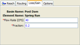
The Constant Loss/Gain Method uses an empirical relationship to calculate channel loss using a fixed flow rate reduction and a ratio of the flow. It does not include any capability to representing gaining streams. A fixed flow rate is subtracted from the routed flow and then the remainder is multiplied by a ratio. The reduced flow becomes the outflow for the reach. This method is compatible with all Routing Methods. The Component Editor is shown below.

The Flow Rate parameter specifies the amount of flow to be subtracted from the inflow. It may be zero or greater than zero; if the specified value is zero then no flow rate reduction will occur. If the specified value is greater than the inflow for a time step, then no outflow will result for that interval.
The Fraction is used to reduce the inflow in linear proportion to the flow rate. After the constant value is subtracted from the routed inflow, the remainder is multiplied by the value one minus the fraction. The fraction must be between zero and one.
Percolation Loss/Gain
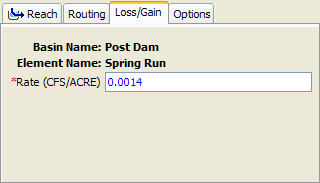
The Percolation Method uses a constant infiltration rate in combination with the inundated area in the reach to compute channel loss. It does not include any capability to representing gaining streams. This method is only compatible with the Modified Puls and Muskingum-Cunge Routing Methods. When used with the Modified Puls method, the optional Elevation-Discharge Function and Invert Elevation must be specified in the routing parameters. The inundated area is calculated differently depending on the Routing Method. In combination with the Modified Puls method, the current storage and outflow are combined with the elevation-discharge curve to compute inundated area. With the Muskingum-Cunge method, the wetted perimeter is multiplied by the reach length to compute area. The Component Editor is shown below.

The Rate parameter specifies percolation in terms of a flow rate per area. The inundated area is multiplied by the rate to determine the channel loss for each time interval.