Download PDF
Download page Selecting a Reach Routing Method.
Selecting a Reach Routing Method
While a reach element conceptually represents a segment of stream or river, the actual calculations are performed by a Routing Method contained within the reach. Nine different Routing Methods are provided (including a "None" option). Each of the methods implements a hydrologic Routing Methodology as compared to a hydraulic approach that implements the full unsteady flow equations. Each method included in the program provides a different level of detail and not all methods are equally adept at representing a particular stream.
The Routing Method for a reach is selected on the Component Editor for the reach element. Access the Component Editor by clicking the Reach Element icon on the Components tab of the Watershed Explorer. You can also access the Component Editor by clicking on the element icon in the Basin Map, if the map is currently open. You can select a Routing Method from the list of nine available choices. If you choose the None method, the reach will translate flow instantaneously and without attenuation. Use the selection list to choose the method you wish to use. Each reach may use a different method or several reaches may use the same method.
When a new reach is created, it is automatically set to use the default Routing Method specified in the Program Settings. You may change the Routing Method for a reach at any time using the Component Editor for the reach element. Since a reach can only use one Routing Method at a time, you will be warned when changing methods that the old parameter data will be lost. You can turn off this warning in the Program Settings. You can change the Routing Method for several reaches simultaneously. Click on the Parameters menu and select the Routing | Change Method command. The Routing Method you choose will be applied to the selected reaches in the basin model, or to all reaches if none are currently selected.
The parameters for each Routing Method are presented on a separate Component Editor from the Reach Element editor. The Routing editor is always shown next to the Reach editor. The information shown on the Routing editor will depend on which method is currently selected.
Kinematic Wave Routing
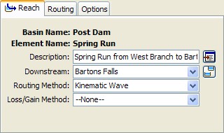
The Kinematic Wave Routing Method approximates the full unsteady flow equations by ignoring inertial and pressure forces. It also is assumed that the energy slope is equal to the bed slope. Consequently, this method is best suited to fairly steep streams. It is often used in urban areas where natural channels have been modified to have regular shapes and slopes. The Component Editor is shown in the following figure. There are two options for an initial condition: Inflow Equals Outflow and Specified Discharge. If you use the first option, it will be assumed that the initial outflow is the same as the initial inflow to the reach from upstream elements. This is essentially the same as assuming a steady-state initial condition. If you use the second option, you will also have to enter a discharge value. The Length should be the total length of the reach element. Usually this value will be measured from maps of the watershed.

The Slope should be the average friction slope for the whole reach. This value may be estimated from maps if they provide sufficient vertical resolution. Field survey data may be necessary to actually determine elevations of the channel bed for calculating the slope. If the slope varies significantly throughout the stream represented by the reach, it may be necessary to use multiple reaches with different slopes.
The Manning's n Roughness Coefficient should be the average value for the whole reach. This value can be estimated from pictures of streams with known roughness coefficient (Barnes, 1967) or by calibration.
The Number of Subreaches is used as a minimum when the program determines the distance step to use during routing calculations. The distance step is first estimated from the travel time. If the estimated distance step is greater than the length divided by the number of subreaches, then the distance step is decreased appropriately. The travel time is computed from the Index Celerity. When Index Flow is entered, the index flow is converted to index celerity using the properties of the reach.
Five options are provided for specifying the cross section shape: Circle, Deep, Rectangle, Trapezoid, and Triangle. The Circle shape cannot be used for pressure flow or pipe networks, but is suitable for representing a free water surface inside a pipe. The Deep shape should only be used for flow conditions where the flow depth is approximately equal to the flow width. Depending on the shape you choose, additional information will have to be entered to describe the size of the cross section shape. This information may include a Diameter (circle), Bottom Width (deep, rectangle, trapezoid), or Side Slope (trapezoid, triangle). The Side Slope is dimensionless and entered as the units of horizontal distance per one unit of vertical distance.
Lag Routing
The Lag Routing Method only represents the translation of flood waves. It does not include any representation of attenuation or diffusion processes. Consequently, it is best suited to short stream segments with a predicable travel time that doesn't vary with flow depth. The Component Editor is shown in the following figure.

There are two options for initial condition: Inflow Equals Outflow and Specified Discharge. If you use the first option, it will be assumed that the initial outflow is the same as the initial inflow to the reach from upstream elements. This is essentially the same as assuming a steady-state initial condition. If you use the second option, you will also have to enter a discharge value.
The Lag Routing parameter is the time (in minutes) that the inflow hydrograph will be translated. Inflow to the reach is delayed in time by an amount equal to the specified lag, and then becomes outflow.
Lag and K Routing
The Lag and K Routing Method is a hydrologic storage Routing Method based on a graphical routing technique that is extensively used by the National Weather Service. The method is a special case of the Muskingum method where channel storage is represented by the prism component alone with no wedge storage (i.e. Muskingum X = 0). The lack of wedge storage means that the method should only be used for slowly varying flood waves. Like all hydrologic Routing Methods, it does not account for complex flow conditions such as backwater effects and/or hydraulic structures. The Component Editor, when using constant Lag and K values, is shown in the following figure.
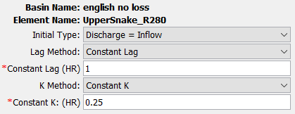
There are two options for initial condition: Inflow Equals Outflow and Specified Discharge. If you use the first option, it will be assumed that the initial outflow is the same as the initial inflow to the reach from upstream elements. This is essentially the same as assuming a steady-state initial condition. If you use the second option, you will also have to enter a discharge value.
The Lag Term accounts for the travel time of the flood wave as it moves downstream. The K Term accounts for attenuation of the flood wave. Lag and K parameters can be entered as constants or variable functions. When using variable Lag and K functions, Lag is entered as an Inflow-Lag curve and K is entered as an Outflow-Attenuation curve. Evaluation of historical flood hydrographs provides the basis for Lag and K relationships within a reach. Care must be exercised when using lag functions with multiple intercepts (i.e. lag is the same for more than one flow rate). This may result in numerically attenuated peak flow rates.
Modified Puls Routing
The Modified Puls Routing Method is also known as storage routing or level pool routing. It uses conservation of mass and a relationship between storage and discharge to route flow through the stream reach. Attenuation is achieved though the storage and delayed release of water in the reach instead of through a rigorous conservation of momentum approach. It can be useful for representing backwater due to flow constrictions in a channel so long as the backwater affects are fully contained within the reach. The Component Editor is shown in the following figure.
A Storage-Discharge Function defines the amount of outflow for a specific amount of storage in the reach. Storage is the independent variable and the values entered must cover the entire range of storages that may be encountered during a simulation. Usually the first storage will be zero and the maximum storage should be slightly more than the volume in the stream reach when it is at maximum flow. Generally, the outflow values corresponding to each storage value are computed with the assistance of a hydraulic model that computes water surface profiles. The function must be monotonically increasing. The storage-discharge function must be defined in the Paired Data Manager before it can be used in the reach element.

The Number of Subreaches must be entered. It affects attenuation where one subreach gives the maximum attenuation and increasing the number of subreaches approaches zero attenuation. This parameter is necessary because the travel time through a subreach should be approximately equal to the simulation time step for an idealized channel. An initial estimate of this parameter can be obtained by dividing the actual reach length by the product of the wave celerity and the simulation time step. For natural channels that vary in cross section dimension, slope, and storage, the number of subreaches can be treated as a calibration parameter. The number of subreaches may be used to introduce numerical attenuation which can be used to better represent the movement of floodwaves through the natural system.
There are two options for initial condition: Specified Discharge and Inflow Equals Outflow. If you use the first option, you will also have to enter a discharge value. The initial storage in the reach will be calculated from the specified discharge and the storage-discharge function. If you use the second option, it will be assumed that the initial outflow is the same as the initial inflow to the reach from upstream elements. This is essentially the same as assuming a steady-state initial condition. The initial storage will be computed from the first inflow to the reach and storage-discharge function.
Optionally an Elevation-Discharge Function can be selected. If used, it should represent the depth of water for any given outflow from the reach. The function must be monotonically increasing. The elevation-discharge function must be defined in the Paired Data Manager before it can be used in the reach element.
If the optional Elevation-Discharge Function is selected, then an invert elevation should also be specified. The flow depth is added to the invert elevation to compute the stage.
Muskingum Routing
The Muskingum Routing Method uses a simple conservation of mass approach to route flow through the stream reach. However, it does not assume that the water surface is level. By assuming a linear, but non-level, water surface it is possible to account for increased storage during the rising side of a flood wave and decreased storage during the falling side. By adding a travel time for the reach and a weighting between the influence of inflow and outflow, it is possible to approximate attenuation. The Component Editor is shown in the following figure.
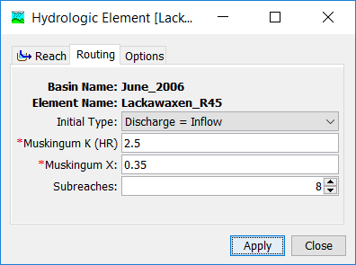
There are two options for initial condition: Inflow Equals Outflow and Specified Discharge. If you use the first option, it will be assumed that the initial outflow is the same as the initial inflow to the reach from upstream elements. This is essentially the same as assuming a steady-state initial condition. If you use the second option, you will also have to enter a discharge value.
The Muskingum K is essentially the travel time through the reach. It can be estimated from knowledge of the cross section properties and flow properties. It may be a calibration parameter in some cases.
The Muskingum X is the weighting between inflow and outflow influence; it ranges from 0.0 up to 0.5. In practical application, a value of 0.0 results in maximum attenuation and 0.5 results in no attenuation. Most stream reaches require an intermediate value found through calibration.
The Number of Subreaches must be entered. It affects attenuation where one subreach gives more attenuation and increasing the number of subreaches decreases the attenuation. An initial estimate of this parameter can be obtained by dividing the actual reach length by the product of the wave celerity and the simulation time step. For natural channels that vary in cross section dimension, slope, and storage, the number of subreaches can be treated as a calibration parameter. The number of subreaches may be used to introduce numerical attenuation which can be used to better represent the movement of floodwaves through the natural system.
Muskingum-Cunge Routing
The Muskingum-Cunge Routing Method is based on the combination of the conservation of mass and the diffusion representation of the conservation of momentum. It is sometimes referred to as a variable coefficient method because the routing parameters are recalculated every time step based on channel properties and the flow depth. It represents attenuation of flood waves and can be used in reaches with a small slope. The Component Editor is shown below.
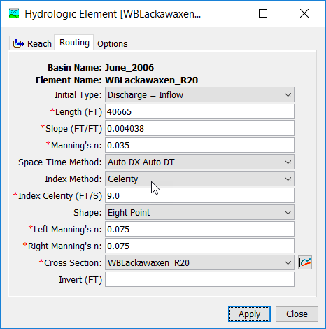
There are two options for initial condition: Inflow Equals Outflow and Specified Discharge. If you use the first option, it will be assumed that the initial outflow is the same as the initial inflow to the reach from upstream elements. This is essentially the same as assuming a steady-state initial condition. If you use the second option, you will also have to enter a discharge value.
The Length should be the total length of the reach element. Usually this value will be measured from maps of the watershed.
The Slope should be the average friction slope for the whole reach. This value may be estimated from maps if they provide sufficient vertical resolution or by field surveying. If the slope varies significantly throughout the stream represented by the reach, it may be necessary to use multiple reaches with different slopes.
The Manning's n Roughness Coefficient should be the average value for the whole reach. This value can be estimated from pictures of streams with known roughness coefficient (Barnes, 1967) or by calibration. When the Tabular shape is selected, no Manning's n roughness values need to be entered.
The Space-Time Interval selection provides three options. When the Auto DX Auto DT Method is selected, the program will automatically select space and time intervals that maintain numeric stability. Alternately, when the Specified DX Auto DT Method is selected, the program will use the specified number of subreaches (i.e. DX) while automatically varying the time interval to take as long a time interval as possible while also maintaining numeric stability. Finally, when the Specified DX Specified DT Method is selected, the program will use the specified number of subreaches and subintervals throughout the entire simulation.
The Index Method is used in conjunction with the physical properties of the channel and the previously mentioned space-time interval selection. The selected index method and specified parameter will be used by the program to discretize the routing reach in both space and time. Appropriate reference flows and celerities are dependent upon the physical properties of the channel as well as the event(s) in question. Experience has shown that a reference flow (or celerity) based upon average values of the hydrograph in question (i.e. midway between the base flow and the peak flow) is, in general, the most suitable choice. Reference flows (or celerities) based on peak values tend to numerically accelerate the wave much more than would occur in nature, while the converse is true if a low reference flow (or celerity) is used (Ponce, 1983).
Six options are provided for specifying the cross section shape: Circle, Eight Point, Rectangle, Tabular, Trapezoid, and Triangle. The Circle shape cannot be used for pressure flow or pipe networks, but is suitable for representing a free water surface inside a pipe. Depending on the shape you choose, additional information will have to be entered to describe the properties of the cross section. This information may include a Diameter (circle), Bottom Width (rectangle, trapezoid), or Side Slope (trapezoid, triangle). The Side Slope is dimensionless and entered as the units of horizontal distance per one unit of vertical distance.
If the Tabular shape is used, you will also have to select multiple curves that describe the way in which discharge, area, and top width changes with elevation. These curves must be defined as elevation-discharge, elevation-area, and elevation-width functions, respectively, in the Paired Data Manager before they can be used in the reach element. When routing sediment or computing losses through the bottom of the channel, an elevation-wetted perimeter function must also be defined and selected. These curves must be monotonically increasing. Within each of the aforementioned curves, the x-axis defines the elevation while the y-axis defines the variable of interest. Elevations must be monotonically increasing.
The Eight Point shape requires a cross section simplified with only eight station-elevation values. The cross section is usually configured to represent the main channel plus left and right overbank areas. A separate Manning's n value is entered for each overbank. The cross section should extend from the channel invert up to the maximum water surface elevation that will be encountered during a simulation. The cross section must be created in the Paired Data Manager before it can be used in the reach.
Optionally, an Invert Elevation may be specified. When used, the flow depth computed during the routing is added to the invert elevation to compute the stage.
Normal Depth Routing
The Normal Depth Routing Method uses a Modified Puls Routing approach where storage-discharge relationships are developed using a normal depth assumption for the reach. The user enters geometric data for the channel. HEC-HMS computes the storage-discharge relationship for the given channel using Manning's equation for normal depth. HEC-HMS computes the number of Modified Puls subreaches by dividing the travel time by the simulation time interval. The Component Editor is shown in the following figure.

There are two options for initial condition: Inflow Equals Outflow and Specified Discharge. If you use the first option, it will be assumed that the initial outflow is the same as the initial inflow to the reach from upstream elements. This is essentially the same as assuming a steady-state initial condition. If you use the second option, you will also have to enter a discharge value. The Length should be the total length of the reach element. Usually this value will be measured from maps of the watershed or through GIS tools. The Slope should be the average slope for the whole reach. This value may be estimated from GIS datasets if they provide sufficient vertical resolution or by field surveying. If the slope varies significantly throughout the stream represented by the reach, it may be necessary to use multiple reaches with different slopes. The Manning's n Roughness Coefficient should be the average value for the whole reach. This value can be estimated from pictures of streams with known roughness coefficient (Barnes, 1967), GIS datasets, or by calibration. The Index Flow should represent the expected maximum flow in the reach. A storage-discharge relationship will be created ranging from zero to 1.5 times the index flow. The travel time will be computed using the reference flow, channel geometry, and reach length, from which the number of subreaches will be automatically computed as the travel time divided by the simulation time interval.
Optionally, an Invert Elevation may be specified. The invert is referenced to the downstream end of the routing reach. When used, the flow depth computed during the routing is added to the invert elevation to compute the stage.
Five options are provided for specifying the cross section shape: Circle, Eight Point, Rectangle, Trapezoid, and Triangle. The Circle shape cannot be used for pressure flow or pipe networks, but is suitable for representing a free water surface inside a pipe. Depending on the shape you choose, additional information will have to be entered to describe the size of the cross section shape. This information may include a Diameter (circle), Bottom Width (rectangle, trapezoid), or Side Slope (trapezoid, triangle). The Side Slope is dimensionless and entered as the units of horizontal distance per one unit of vertical distance. The Eight Point shape requires a cross section simplified with only eight station-elevation values. The cross section is usually configured to represent the main channel plus left and right overbank areas. A separate Manning's n value is required for each overbank when the eight point cross section shape is selected. The cross section should extend from the channel invert up to the maximum water surface elevation that will be encountered during a simulation. The cross section must be created in the Paired Data Manager before it can be used in the reach.
Straddle Stagger Routing
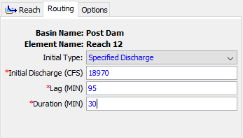
The Straddle Stagger Method uses empirical representations of translation and attenuation processes to route water through a reach. Inflow is delayed a specified amount of time. The delayed flows are averaged over a specified amount of time to produce the final outflow. The Component Editor is shown in the following figure.
There are two options for initial condition: Inflow Equals Outflow and Specified Discharge. If you use the first option, it will be assumed that the initial outflow is the same as the initial inflow to the reach from upstream elements. This is essentially the same as assuming a steady-state initial condition. If you use the second option, you will also have to enter a discharge value.
The Lag parameter specifies travel time through the reach. Inflow to the reach is delayed in time by an amount equal to the specified lag.
The Duration parameter specifies the amount of spreading in a flood peak as it travels through the reach. The delayed inflows are averaged over this specified time duration. The duration parameter loses physical meaning when it is greater than twice the lag time.
