Download PDF
Download page Global Settings.
Global Settings
Global settings apply to all sessions and map windows in the project. For example, if the unit system is changed from Metric to English, all the map windows that may be displaying data in millimeters will refresh using inches instead.
Program global objects are objects that are used globally by all other entities in the program. A fixed set of program global objects are available from which to select for a session or a map window. An example of this would be the contour color palettes that have been defined. Multiple color palettes can be defined. Any session or map window can then select to use one of them. The following are examples of global object sets:
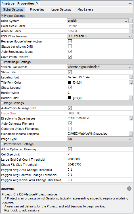
The global settings set the default for the unit system and give access to the global palette, scale and attribute editors. The global settings are visible from the very top node in the Project Explorer as well as every Session and Map window node. The table below provides definitions for the features available in the global settings tab.
Section | Option | Definition |
|---|---|---|
Project Settings | These settings apply project-wide. | |
Units System | The units system to use for all sessions and map windows in use. It is not possible to have some map windows display English units and others use SI as it was deemed to be too error prone. However, if the program does not recognize the measurement units or cannot convert them it will display the measurement data in the given units. HEC-MetVue can be used to display a variety of non-precipitation data however it can only aggregate measurement TINs if the units are consistent or the units are recognized. For example the program can directly add TINS where one is in inches and the other in mm. | |
Color Scale Editor | Links to the external Color Scale Editor for defining color scales. Color scales are used to define the various attributes (such as colors and line styles) used to render contours and other measurement related data. | |
Attribute Editor | Links to the external attribute editor for defining attribute objects and new attribute schemas. Attributes are used to define the line styles, colors, and symbols used to render the shapefile information. | |
DSS Write Version | This setting allows the user to control if the output is DSS version 6 or version 7. Note that DSS version 7 is required for writing TINs to DSS. | |
Reverse Mouse Wheel Action | The mouse wheel provides an easy way to zoom in/out on a map window. The default action is to zoom in when the mouse wheel is pulled away from the screen. Checking this option will cause the mouse wheel to zoom out when pulled away from the screen. | |
Status Bar Shows DMS | If this is checked, when mouse cursor tracking is enabled, the cursor longitude/latitude value are displayed in degrees, minutes, and seconds. When unchecked, coordinates are displayed in decimal degrees. | |
Auto Encompass Maps | When this is checked and a map is added to the map window, the map window view will be adjusted so that the map is displayed in the map window. If unchecked, when new maps are added to the map window, the extents of the view remain unchanged. | |
| Save Paths Relative | When checked, this will save all pathnames as relative if possible. Pathnames will be made relative if they are in the same directory as the project file, or a sub-directory. | |
Print/Image Settings | The settings in this section apply to both printing and imaging | |
Switch Black/White | This option is used to modify the colors that objects are drawn with when printing and imaging as opposed to rendering on the screen. Options are:
| |
Show Title | The title in the title bar of the map window will be placed in the map window when printed. | |
Labeling Font | Selects the font to use for the title. | |
Title Font Color | Selects the color to use for the title font. | |
Show Legend | If this is selected the legend is made a part of the page print or image capture. The location of the legend is relative to the session being rendered. It would be as if a rectangle that encompasses the legend and the session windows was used to map the desired image to the paper. | |
Border Width | This simply selects the width of the border used to define various session and map window bounds within the print. | |
Border Color | The color to draw the border. | |
Image Settings | These settings apply only to image capture. | |
Auto compute image size | This option determines the size of the image based on the size the image is drawn on the screen and matches it. | |
Image Size | If a specific image size is desired this is where to define it. Note that font sizes are specified in points and that if the image size is significantly different that the image on the screen, the fonts that are rendered may be different than expected. | |
Directory to Save Images | This is the location to store the images that are created. | |
Auto Generate Filename | If this is selected the filename to use for image save is automatically generated based on the TIN image times of the topmost map window of the session. | |
Generate Unique Filenames | Selecting this will modify the filename. The idea here is to make it convenient to create multiple images without having to keep entering a filename. For example if this is chosen and the filename template is d:\temp\pics.png, the filenames actually generated will be d:\temp\pics.png, d:\temp\pics.001.png, d:\temp\pics.002.png etc. | |
Filename/Filename Template | This specifies the filename to use for taking a snapshot. If the 'generate unique filenames' option is selected then this specifies the base filename to use. This filename will be modified as new images are created. | |
Image Type | Options are (note: options may change depending on the version of Java being used)
| |
Performance Settings | These settings apply to balance performance and memory consumption of the program. | |
Allow Optimized Drawing | ||
Cell Size Limit | ||
| Large Grid Cell Count Threshold | Large grids have special handling to reduce memory impacts and loading speed. This is described in Large Grid Handling. | |
| Shape File Size Threshold | ||
| Polygon Avg Area Change Threshold | The percent of change in polygon area allowable when performing simplification. The default is 0.1. | |
| Polygon Avg Centroid Change Threshold | The percent of change in polygon centroid allowable when performing simplification. The default is 0.1. | |
| Polygon Avg Inertial Axis Change Threshold | The percent of change in polygon inertial axis allowable when performing simplification. The default is 0.1. |