Download PDF
Download page Mesh Quality.
Mesh Quality
Although HEC-RAS can compute on highly irregular meshes, poor mesh quality will decrease the accuracy of the numerical solution and can lead to poor convergence and numerical instabilities. Mesh quality affects both the flow and sediment, but it is especially important when simulating sediment transport. Generating a mesh is an iterative process and may require running simulations in order to identify problem areas or areas which require their resolution adjusted in order to resolve the flow or sediment transport.
Mesh Alignment
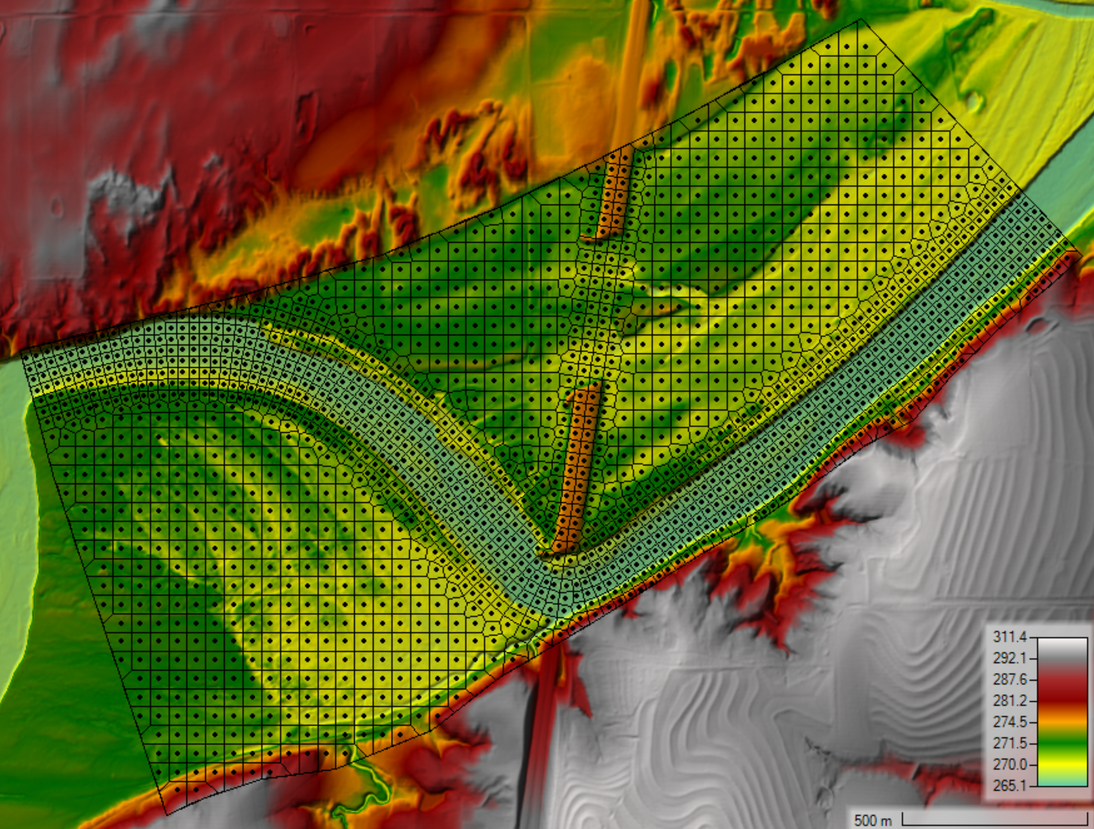
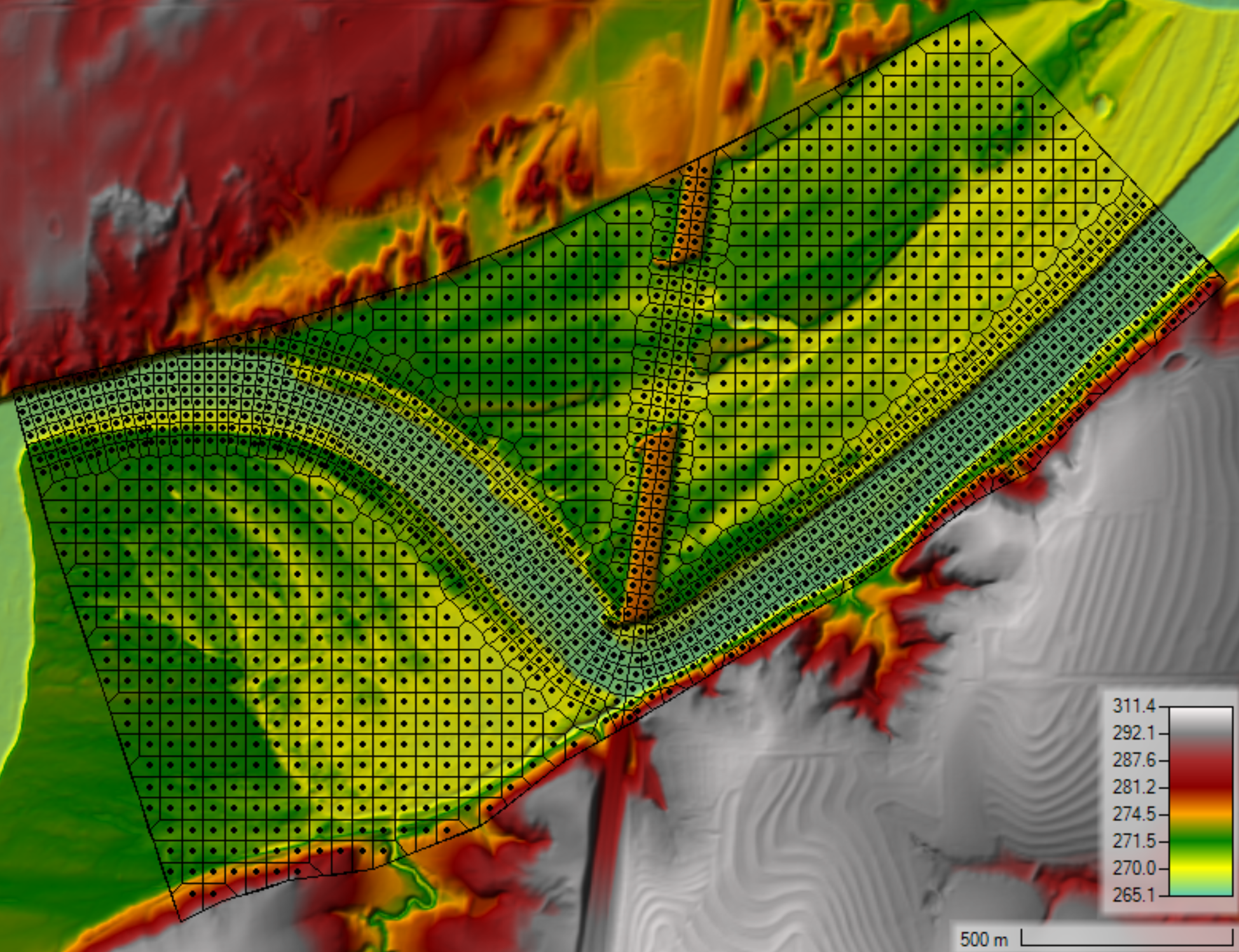
With 2D flow and sediment transport, the HEC-RAS will produce better results if the mesh is oriented or aligned with the flow. This reduces numerical diffusion and improved computational accuracy. In the example below, a refinement region is used to increase the spatial resolution (25 ft) within the channel. The refinement region allows for a more resolution within the channel while maintaining coarse resolution outside of the channel, thus reducing the total number of computational cells and computational costs. The refinement region also also aligns the channel banks which also improves the model results. However, the issue with this approach is the that the cells are not aligned with the flow producing more numerical diffusion. In addition, the regions in between the square or rectangular cells within the refinement polygon and the boundaries of the refinement polygon can have relatively irregular cells and relatively poor mesh quality.

Aligning the Mesh with a Breakline
To improve the mesh alignment with the flow, a break line is inserted along the centerline of the channel as shown in the figure below. The breakline is added with 6 repeat points and a 30-ft spacing.

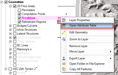
To "repeat points" right click on the break line in the RASMapper Tree and select Open Attribute Table.
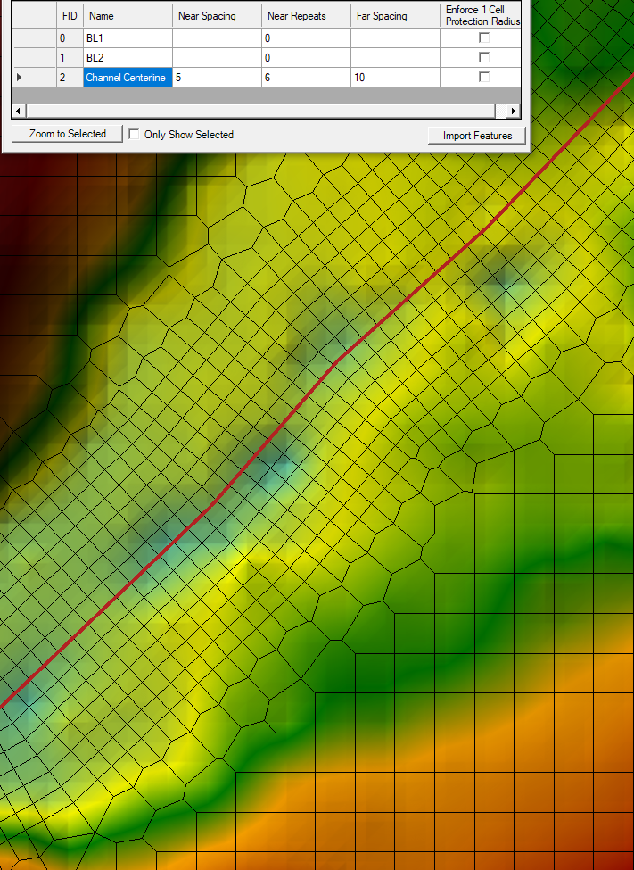
Then specify the size of the aligned cell and the number of repetitions. Enforcing the protection radius can cause awkward transitions between the aligned mesh and the original, orthogonal mesh. It is often useful not to enforce the 1 cell protection radius unless the channel is bounded by a levee or other high ground you need to resolve precisely.
When using breaklines around bends, the inside of the bend can have computational points which are very close to each other. Similarly, the outside of bends have points spread too far apart. This areas may need manual adjustment by inserting and removing points where necessary.
When editing the mesh manually, it is often useful to turn on and off the computational edges and terrain in order to identify gaps in spatial resolution, to identify small edges, and to align edges with the terrain features and principle flow direction.
An example of how the corrected mesh with improved transitions areas is shown in the figure below.
Aligning the Mesh with a Refinement Region
Refinement Regions aligned in the direction of flow can also align cells with the flow direction, however, these will often require some manual editing after enforcing the refinement. Refinement regions can be more detailed or have the same cell spacing as the surrounding mesh.
Identifying Poor Transition Areas and Adding Computational Points Manually
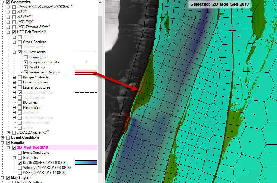
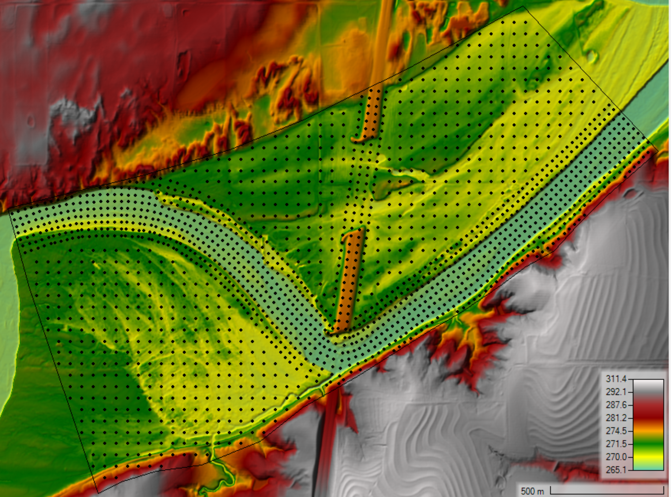
When creating a computational mesh, often the transition areas near refinement reaches or breaklines have spatial resolutions which are coarser than the the neighboring areas. Below is an example of a computational mesh which was generated by adding two breaklines; one following the channel centerline, and one following a roadway embankment.
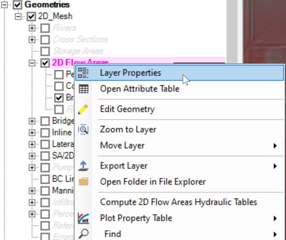
At first glance the computational looks reasonable. However, the transition areas between the breaklines and coarser parts of the mesh have some problem areas which can be easily identified by turning on the computational points and turning off the edges (faces). The mesh edges can be done by right-clicking on the 2D Flow Area and selecting Layer Properties as shown in the figure below.
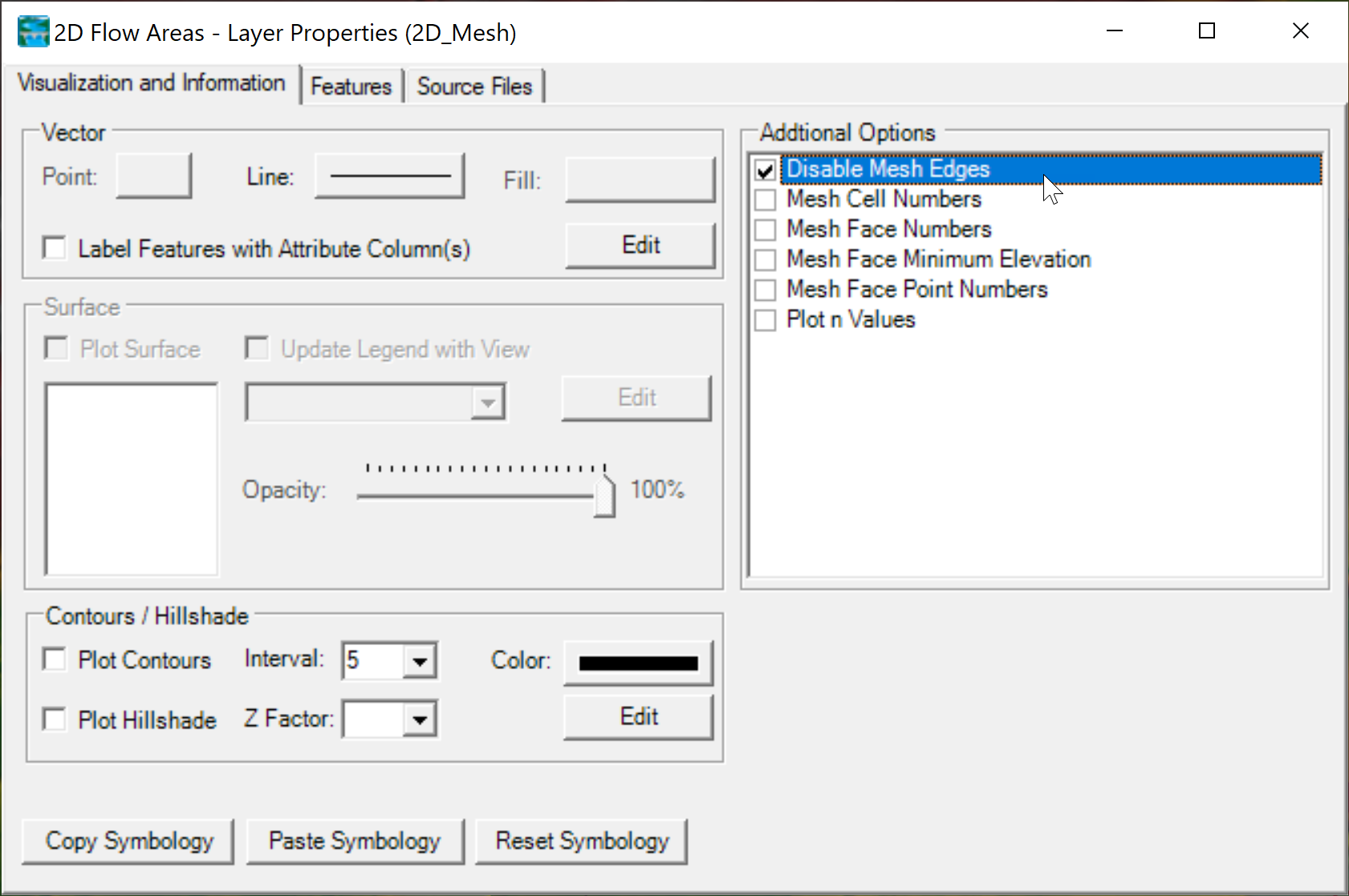
This will open the 2D Flow Areas - Layer Properties editor. In the section Additional Options select the option Disable Mesh Edges.
Once the Computational Points are turned on the Mesh Edges turned off, the computational mesh should look like this:
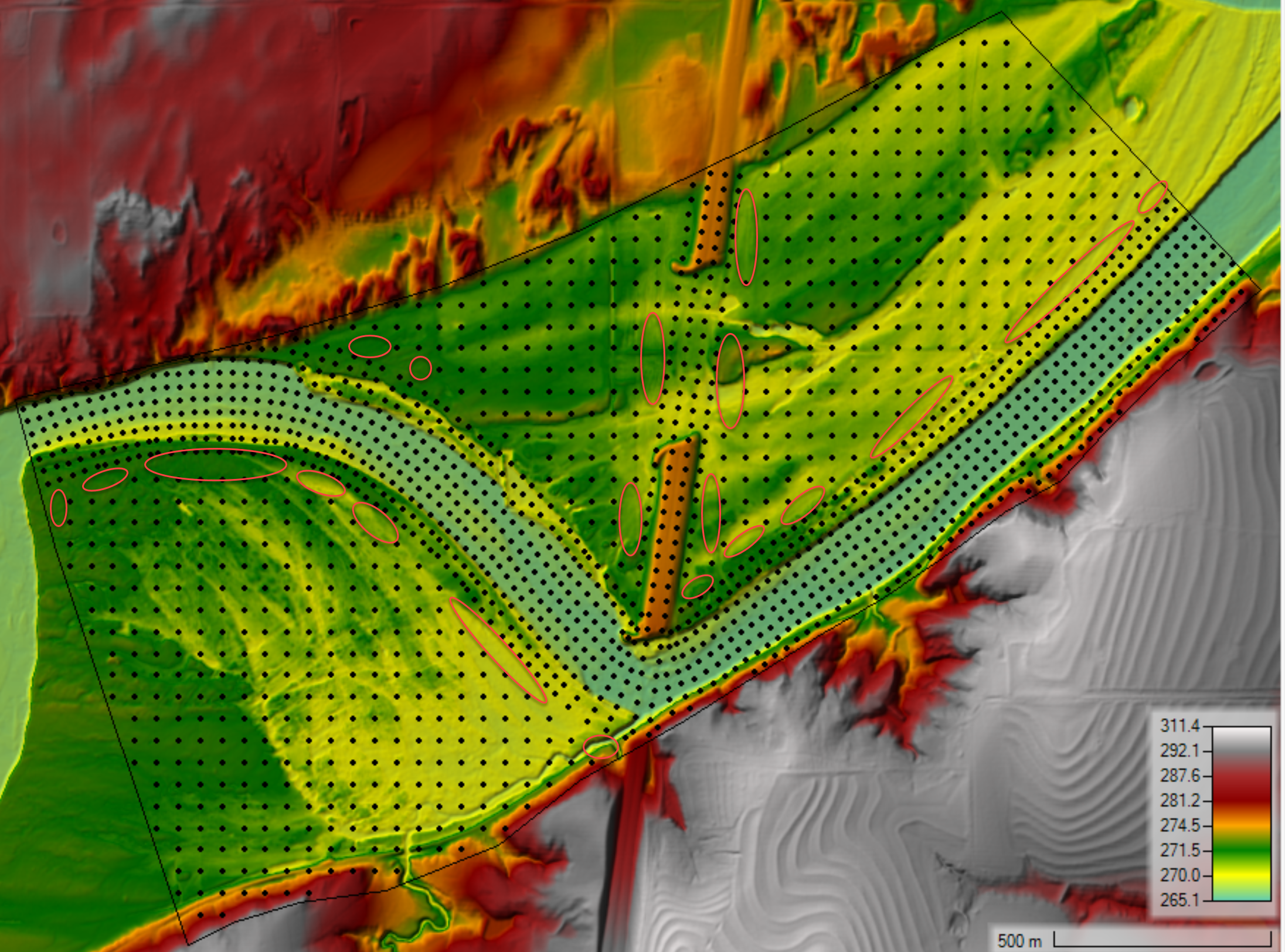
The poor transition areas are identified as holes in the computational points. These areas are highlighted with ellipses in the figure below.
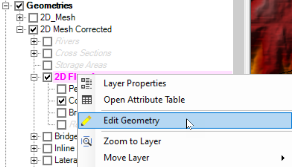
The best way to fill in the "holes" in the computational points is to edit the mesh and add points manually. This is done by right-clicking on the mesh and selecting Edit Geometry as shown in the figure below.
Next, add and move existing Computational Points so that the there are smooth transitions in resolution and there are no gaps in resolution.
Small Cell Faces
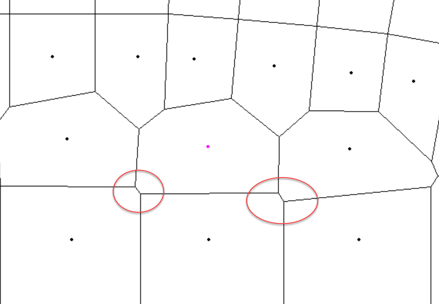
The HEC-RAS mesh generator has a tolerance for the Minimum Face Length. The Tolerance is the minimum face length specified as a percentage of the distance between neighboring computational points. The default value in versions 6.1 and earlier is 5%. This value is relatively small for sediment simulations and can lead to reduced stability and also increases the computational time and memory. The figure below shows an example of small faces produces by a Minimum Face Length Tolerance of 5%.
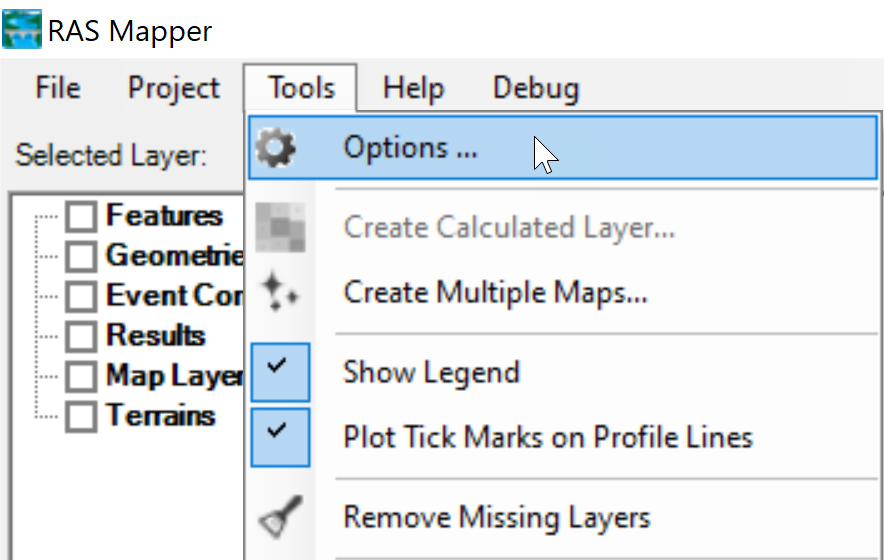
Small faces can be reduced by either manually nudging computational points or by increasing the Minimum Face Length Tolerance. The value can be changed in RAS Mapper Options editor (see figure below on how to open editor).
The Minimum Face Length Tolerance is found in the Mesh Tolerances section of the Options editor (see figure below).
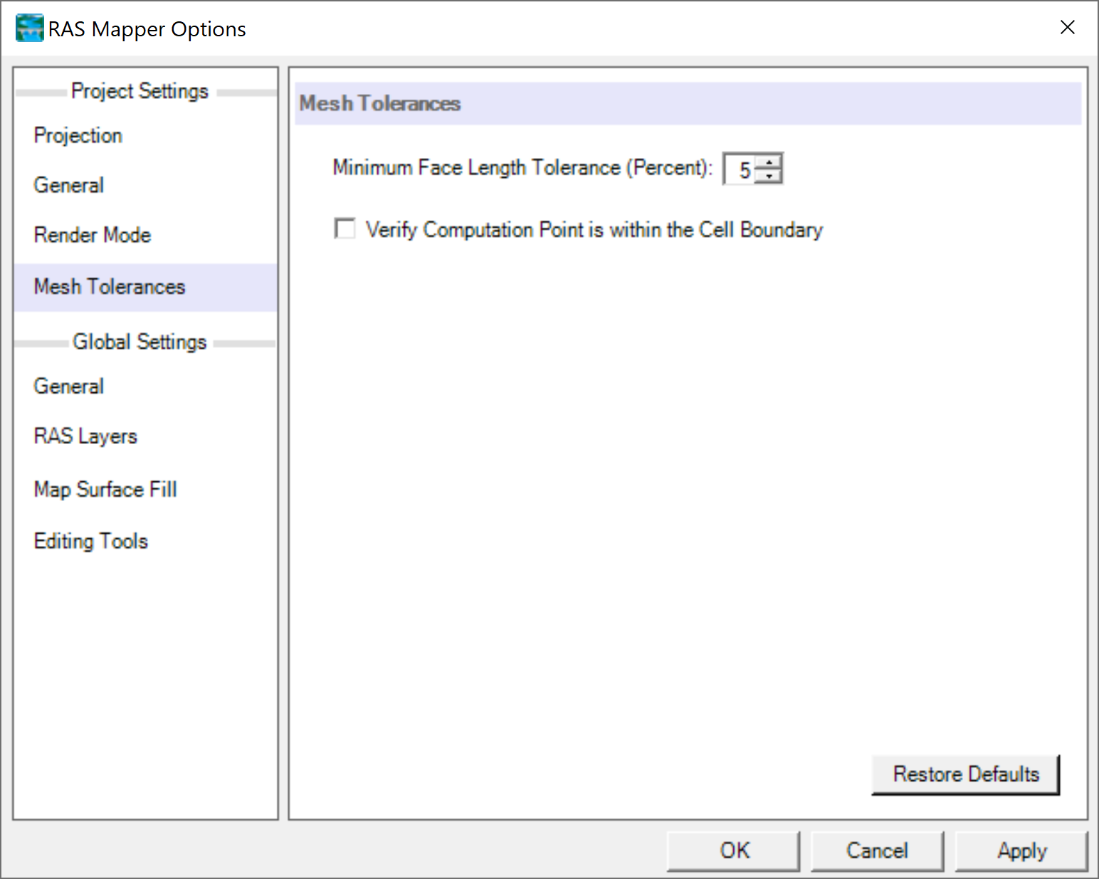
For 2D sediment simulations, a Minimum Face Length Tolerance of about 15 to 25% has been found to work well.
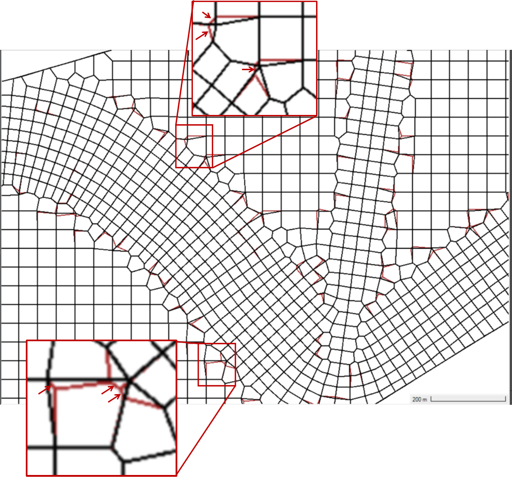
An example is shown in figure below where the red mesh correspond to a Minimum Face Length Tolerance of 5% and the black mesh corresponds to Minimum Face Length Tolerance of 20%.