Download PDF
Download page Creating a Terrain Dataset to Model a Flume Experiment.
Creating a Terrain Dataset to Model a Flume Experiment
Typically, we use HEC-RAS to model real-world situations. However, sometimes we might find the need to model large-scale (small dataset) problems like a flume. The main problem in create a terrain model is that HEC-RAS uses a raster for storing data; however, this raster is going to be interpolated based on a cross section layout which will result in a terrain model that is not perfect. This document will discuss how we can use HEC-RAS to create a RAS Terrain which we then can used to create a 2D model and try to address some things to think about when creating it.
How Does it Work?
Before you get started you will need to know the dimensions of the dataset and arrive on the grid cell size that the resulting terrain model is going to be. All of the data will be created from cross sections and the variations in terrain will be based on the cell size selected. For this example, we have a flume that is 10m long, 0.5m wide, and 0.5m deep with a 0.1m drop over it's length. You will want enough cells to properly represent the terrain across the channel. For this case, we will use a cell size of 0.01m which will give us adequate defining in cross section (50 cells across).

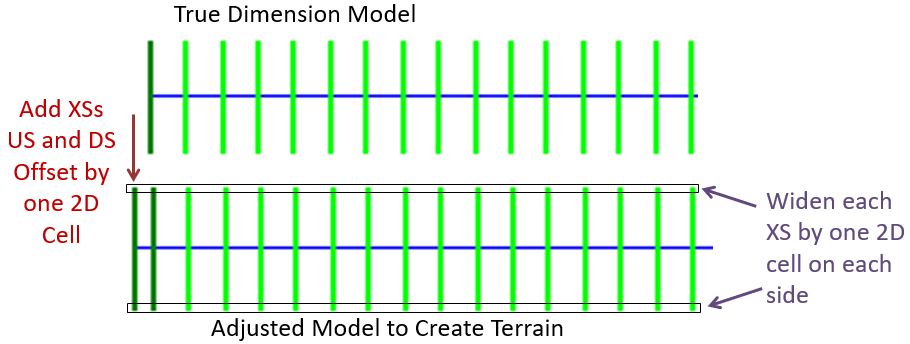
You will use the flume dimensions and predetermined grid cell size to create a set of HEC-RAS cross sections. Once the HEC-RAS model geometry is constructed, you will export the geometry to a ground surface (TIF), and then use the ground surface to create a RAS Terrain. Creating the ground surface from cross sections ends up truncating the data around the edges by 1/2 a grid cell size, so you will need to consider that when making the data and make your model 1 grid cell longer and wider on all four sides of the model (2 cells longer, 2 cells wider).
Buffer the model domain by 1 grid cell length
Make your model 1 grid cell size longer at the upstream and downstream end and 1 grid cell wider on the left and right overbank.Step-by-step guide
Perform the following step in HEC-RAS:
- Create a new RAS project, set the Unit System, and start a new Geometry.
- From the Geometric Data Editor, draw a River Centerline, providing a river and reach name.
- Open the GIS Tools | Reach Invert Lines Table to enter the XY coordinates for the river line.
Enter the geospatial coordinates for the river line. (Note: the river should be 1 cell farther upstream and downstream of the model limits - an easy way to do this is add a row at the start and add a row at the end.)
For the example, above, the flume is 4.25m long. Additional, length (0.001m) was added based on 1 grid cell size upstream and downstream. - Create bounding cross sections at the top and bottom of the river reach. The "base" cross sections will be at RS 4.25 and RS 0. You will also need to add them to RS 4.251 and RS -0.001. Further, the cross sections must be wider (0.001m on both sides) than the true dimension.

- Reach lengths will vary for each cross section. For RS 4.25 the reach length is full length of the reach (4.25m). For RS 4.251 and RS 0 use the cell size (0.001m).
- Set Bank Stations.
- Open the GIS Tools | CS Cut Lines Table to enter the XY coordinates for each cross section. The cut lines must match the station-elevation data. (It's easiest to think of the main channel and then then extend the left and right sides by 1 grid cell length.)

- Save the Geometry.
- Open RAS Mapper.
- Right-click on the Geometry and choose Export Layer | Create Terrain GeoTiff from XS's (Overbanks and Channel).
- Provide a filename and cell size (0.01 for this example).
- Right-click on the Terrains group and choose Create a New RAS Terrain.
- Click No to disregard having a projection.
- Add the ground surface raster, choose None for Rounding, No Vertical Conversion, and uncheck Create Stitches.

- Provide a filename → click on the folder button to give the terrain a name other than the generic "Terrain.hdf"

- Click Create.
- You can now inspect your Terrain model.

Some Things to Consider
You now have a terrain model with which you can visualize HEC-RAS results from a 1D model or you can use as the basis for creating a 2D model.
In order to properly plot the data (like in the figure below), you will need to set the precision for the horizontal and vertical data. Because we are using data to many decimal places, match the horizontal precision from the Tools | Options menu.
Take a look at your new RAS Terrain. Raster datasets have a single value per grid cell; however, RAS interpolates data from cell center to cell center so that a continuous profile may be extracted. This will result in a slope on the walls of the flume. You can experiment with elevations of the extended points in the station-elevation data to get the best representation of the channel for your purposes.
 and profile from terrain (brown)")
Creating a 2D Model
When creating a 2D model domain, the model should run from the upstream cross section (RS 10) to the downstream cross section (RS 0), ignoring the boundary cross sections. You can use the geospatial coordinates of the cross sections to create the mesh boundary.
- In RAS Mapper, Add a New Geometry
- Right click on 2D Flow Area and Select Start Editing
- Add a perimeter: Click on Perimeter
 and then choose the draw tool.
 (just 3 points is fine).
 - Select the perimeter, right-click on the perimeter and choose the Geospatial Operations | View/Edit Points menu item. (If you can't find this function, go to the geometry editor and select GIS Tools→Storage Area/2D Area Outlines)
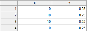
- Enter the true coordinates of the flume (without the extra cells added) points in consecutive order.
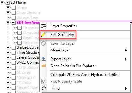
- Edit the 2D Flow Area
- Provide the cell mesh point spacing and enter the appropriate n value
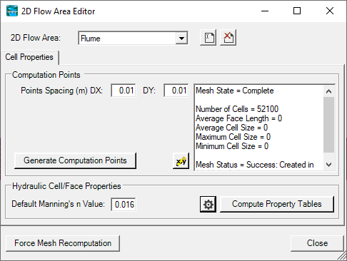
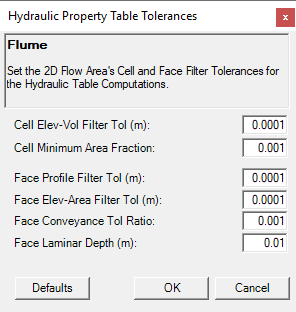
- Enter appropriate hydraulic table parameters
- Create your upstream and downstream boundary conditions location in RAS Mapper.
- Stop Editing.
- Enter flow data for the upstream boundary.
- Set up you Plan and Simulate.