Download PDF
Download page Modeling Weirs in 2D Areas.
Modeling Weirs in 2D Areas
HEC-RAS allows users to model weirs between or within 2D areas. Modelers use these features to simulate flow over high ground, dams, geologic controls, road embankments, and a wide range of linear features that guide, impede, and regulate flow. These are very useful features, but there are also several common modeling mistakes that can cause substantial errors in the computed water surface or velocities.
Summary of Recommendations
Selecting the 2D equations ("Normal 2D Equation Domain") instead of the 1D Weir equation ("Use Weir Equation") when the shallow water flow equations cannot balance momentum over the weir (e.g. waterfall conditions) is the most common error with these structures. The rule of thumb is: (1) If the water surface passes through critical depth over the weir, use the 1D weir equation; (2) If flow over the structure is submerged use the 2D equations.

Modelers tend to use the 2D equations too often. The 1D Weir equation will be more accurate (often by several feet) for free-flowing weirs.
However, even when users select the 1D Weir equation, they often set up their 2D structure and the surrounding cells that force a tailwater condition that is not appropriate for this equation and introduces substantial velocity and depth errors.
This guide leads users through the critical considerations for choosing a 2D Weir method and the best practices for building meshes around these structures.

Adding an Internal Structure to a 2D Area
To add an internal structure to an HEC-RAS geometry, add a new 2D Area Connection in RAS Mapper. The hydraulic structure will be treated as a break line when the 2D Flow Area mesh is re-computed. Or you can choose to right-click on the structure and Enforce the 2D Connection as a Break Line. The break line properties for the structure will use to default cell size for the 2D Area, or you can right-click on the structure and select Edit 2D Connection Breakline Properties to specify a different cell size (usually larger) and/or align cells with the structure. RAS2025 also has meshing capabilities that can elongate the cells at the weir, in the direction of flow, without changing the lateral cell size, so users sometimes make their meshes in RAS2025 and import them into HEC-RAS 6.X.


To edit the structure, open the geometry file and select the SA/2D Conn button ![]() .
.
What is the difference between modeling a 2D structure with only a Terrain Modification or with a 2D Connection and the 2D equation?
Not much. The SA/2D Conn option in HEC-RAS predated the full terrain mod capabilities. Therefore, in situations where it is appropriate to use the 2D equations to model your weir or structure, the current best practice is to just use a channel mod and not add a SA/2D connection unless you need one of the features of that tool. Add a structure if you need culverts or gates or the breaching tools, or if the weir profile is not well defined in the terrain. The case shown below is a classic example of using a hydraulic structure to improve the weir profile when the terrain is not precise. The new channel modification tools now allow you to add changes like this directly to your terrain.

It is worth noting that the grey representation of the structure has no hydraulic function in the model, whether you are using the 2D or Weir equations. The model only uses the center line of the structure as the cell faces along that line. It does not affect the other cells even if they are within the grey footprint of the structure.

Selecting a 2D Overflow Computation Method
The SA/2D Conn button (in the Geometric Schematic) will take you to the Hydraulic Structure editor, where you can modify the simple terrain profile. This editor allows users to modify the weir profile, add culverts, gates, add breach data, and specify several other structure properties. One of the most important decisions modelers must make at this point is which Overflow Computation Method to select. Many users just leave this on the default option Normal 2D Equation Domain. This is the first option listed (used to be default and described as "normal"), and it sounds more advanced, so users do not tend to evaluate this decision. But they can generate very different answers, are appropriate for different conditions, and it is important to select the right option.

| 2D Equation | Weir Equation |
|---|---|
| Approach: Uses the 2D equations by simply using the station-elevation data from the weir/embankment as the cell faces. If you do not override the weir/embankment elevations and do not add other options (e.g. gates, culverts, breaches) this should be identical to just drawing a break line across the terrain or terrain modification. | Approach: Computes flow over the weir/embankment with the 1D weir equation. Uses headwater and tailwater from the upstream and downstream cells to compute flow based on the head differential, length, and an empirical coefficient. |
| Appropriate For: Submerged flow that does not form a waterfall (or, usually, pass through critical depth). Usually a small, inline structure relative to the flow depth. | Appropriate For: Flow controlled by critical depth over the weir (i.e. waterfall flow, plunging flow, free-falling flow). Used for most levees, floodwalls, and lateral structures. |
| Do Not Use If: Flow is controlled by critical depth. If HEC-RAS cannot balance the momentum equation across the weir (e.g. free-falling flow) the 2D equations will substantially over-predict velocities. This will lead to unrealistic velocities, but will also push too much flow over the weir, under-predicting upstream stages. This approach will also be less stable. | Not Ideal If: Flow is highly submerged. The 2D equations balance the momentum and will give a better result and will run faster if the tailwater is high enough to use the 2D equations throughout the reach. The weir equation tends to compute higher headwater for submerged conditions and is less stable. |
| Modeling Considerations: If you are going to use the 2D equations and are only modeling the overflow process, it can be easier to just override the weir elevations with a channel modification. Be careful about cells that span large elevation changes in the direction of flow. Larger cells around the weir tend to e more stable for multiple reasons. | Modeling Considerations: Be careful that the downstream cells reflect the tail water condition and are not too close to the structure break line (see the section on tailwater considerations). Tends to add run time and instability. The weir equation is often appropriate for a wider range of flows if the simulation includes multiple submergence conditions. |
|
|

Recognize the Limitations of a 2DH Model
HEC-RAS is a 2DH (Two-Dimensional Horizontal) model that vertically averages velocities and does not include vertical acceleration terms. These hydraulic structure equations are often appropriate for understanding how a hydraulic structure will transmit flow and backwater as part of a larger hydraulic system. But detailed hydraulic structure or spillway design often requires a 3D or CFD model to resolve the velocities at the necessary level of detail.
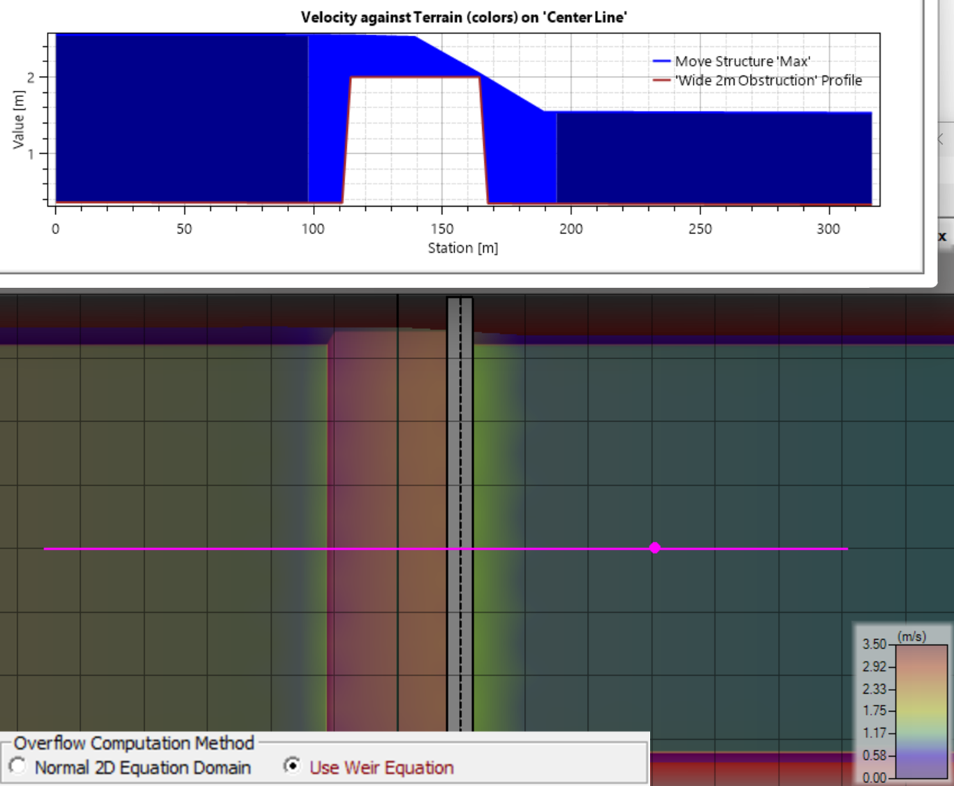
The image below is an example of a structure that should be modeled with the Weir Equation. The obstruction is not large (<1 ft) but the tail water is not regulating flow. The flow is completely controlled by the critical depth condition at the top of the weir. The 2D equations will over-predict velocity and under-predict upstream stage in this condition. This model should use the Weir equation for flows and tailwaters in this range. (Note: it is possible that larger flows or higher tail waters could submerge this weir. Under those conditions the 2D equation would be appropriate).
The choice between the 2D and Weir overflow equations can get complicated when submergence and critical depth conditions shift during the simulation. For example, the Weir equation can be more appropriate during the rising and falling limb a hydrograph while the 2D equations are more accurate (and stable closer to the flow peak). You can currently only choose one method per structure. The HEC-RAS team has discussed an algorithm that switches between these equations automatically based on the hydraulic conditions discussed above. But we are trying to focus our funding and development time on RAS2025. We are currently designing the 2D structure approach in 2025 and it will have some sort of automated algorithm that handles both conditions but may be more sophisticated than just combining these two equations with a logical trigger.
1D Weir Equation Best Practices
This is an example of free fall/plunging weir condition where the 1D Weir equation would be much more appropriate than the 2D equations:

Larger cells tend to be more stable when building an internal structure around the 1D Weir equation. Select cell sizes that are large enough that a single time step will not empty them and that reach far enough up and downstream to capture appropriate head water and tailwater elevations.
Tailwater Management
The weir equation can be very sensitive to water surface in the down-water cell for high submergence. This high submergence may be incorrect if the cell is positioned incorrectly.
Even when users select Use Weir Equation to correctly model weir flow, the weir alignment and meshes around these features must be carefully crafted with the assumptions of these equations in mind. In particular, the weir equation will be very sensitive to the water surface at the downstream cell, which it will use as the tailwater condition. A common (intuitive) modeling approach that introduces error into these models is illustrated below. Digitizing the break line that becomes the 2D Structure along the centerline of a structure included in the terrain, with small cells, will introduce an erroneous tailwater elevation. The tailwater condition computed from the mesh below (computed from the small, downstream cell perched on the structure) will submerge flow over this structure and under predict flow.

There are two model building strategies that can help modelers feed more appropriate tailwater stages to these structures.
1. Move the break line and structure to the downstream edge of the structure
Drawing the break line along the structure centerline makes intuitive sense. But it is important to remember, that the 1D weir equation (Q=CLH3/2) does not have weir width in it (explicitly, the weir width is included indirectly in the weir coefficient). If you use the Weir equation, the grey structure width is for visualization only. It does not affect the computations. The weir equation only uses the cell faces along the break line to compute flow over the structure.
Therefore, if the top of your feature is relatively flat, you can move the break line to the downstream edge of the floodwall, road, dam, or embankment. This will shift the downstream cells off the feature, towards the true tailwater.
 to the downstream edge of the feature can shift the tailwater off the structure itself.")
2. Elongate the downstream cells
The water surface elevation associated with a cell in HEC-RAS is complicated. But it is a representation of the full range of water surface elevations in the cell. Therefore, an elongated cell, that extends farther into the tailwater, will feed the weir equation with a tailwater elevation closer to the actual tailwater in the below example. You can elongate all the cells in the reach with standard break line/refinement regions (with replicates) in the 6.X RAS series (or use larger cells). The meshing tools in RAS2025 make this easier (and 6.X can import meshes from RAS2025).

Larger Cells Around a Structure can Improve Stability
Modelers often use very small cells around overflow structures because - in many cases - smaller cells and time steps improve stability, especially in high velocity settings. However, for structures with steep embankments, larger cells that span those embankments are often more stable with both the 1D Wier and 2D Equation approaches.
Applying both of these best practices can combine the benefits and move the tail water condition even closer to the true tail water.

Weir width does not matter computationally
The Weir equation is Q=CLH3/2. There is no "W" in that equation. The weir equation does not include a term for width (explicitly - wide weirs tend to be less efficient, so it can be included in the empirical coefficient "C"). Therefore, the Weir Width defined in HEC-RAS has no impact on the equation. It is just a display width (the width of the grey rectangle displayed to represent the structure). If models are uncomfortable with the optics of a structure that "overhangs" their downstream face (like the previous figure) they can make the display width thinner without affecting the computations.
2D Equation Best Practices for Structures
The 2D equation balances momentum across cells. This method should be indistinguishable from simply applying the 2D method to a Terrain Modification with cell faces aligned along the centerline profile. Defining a levee or weir with a terrain modification is preferable unless you need special features (e.g. gates, culverts, beaching, or the weir equation). Using the 2D equations across a structure is appropriate and more stable if you expect the structure to be submerged. It also runs faster in many cases.
While the 2D equation will be more stable than the 1D weir equation in many cases, there are some best practices to make 2D computations over structures more stable and accurate. First, placing cell faces with a break line (or the structure centerline) along the downstream edge of the structure will improve model stability and accuracy.
Second, avoid cell sizes and alignments that place cell faces on the steep embankment slopes of a structure. Cell faces aligned with these steep embankment slopes will compute small changes in volume with depth and high velocities. These conditions will cause stability problems (and can drive very small adaptive time steps)

While the 2D equations handle the submerged conditions that are essentially open channel flow, the 1D weir equation can handle a significantly submerged 'almost' open channel condition better than some modelers expect. Submergence is defined as the downstream depth (downstream tailwater minus weir crest) divided by upstream depth (upstream headwater minus weir crest). There is almost no reduction in flow for a submergence less than 85%. However, some modelers may assume based on visual inspection that a 50% submergence is creating a submerged condition where the 2D domain equation would produce better results than the 1D weir equation. But a 50% submergence will not effect the 1D weir flow. The weir equations are often still more appropriate for these fairly submerged conditions.

Improving Submurged Stability
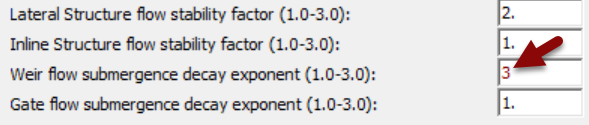
If it makes sense to use a weir for some flows, but it becomes unstable under submerged conditions, you can increase the "Weir Flow Submergence Exponent" (Unsteady Flow Analysis Window→ Options→ Computation Options and Tolerances: General Tab). By default this is set to 1, which is maximum accuracy. But increasing this to 3 makes it more stable with a little accuracy loss.
Unrealistic Max Velocities
With either the 2D or Weir equation, flow over these 2D structures can report unrealistic Max Velocities. This can be puzzling when you scan through the time series of velocity results and do not find any time step that is close to the large, reported, max velocities. There are two important considerations to keep in mind when interpreting these maximum velocities.

- The "Max" result includes the maximum from all computational steps (not just the output increment). Therefore, the max result is often not represented in a mapped result. For models that change gradually, the true simulation maximum is often close enough to one of the output time steps that the difference is not notable. But if the model has instabilities or very short periods of rapid change, very high maximum values can occur between output time steps.
- One of the most common cases of rapid change that generates maximum velocities between output time steps is a wetting front. If cells get wet mid simulation, particularly in a steep section of the model, high-velocity, shallow flows are among the least stable computational conditions. The wetting front often computes artificially high velocities, but these often pass through the model quickly enough that they do not register on one of the results mapped at the output increment.
But it is worth remembering that the velocities in HEC-RAS reflect the assumptions of the momentum equation. The equations in HEC-RAS do not compute the velocity of free-falling water correctly, and the velocities associated with flow over a weir should be interpreted carefully.