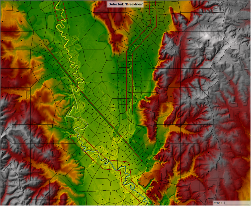
In watershed-scale 2D meshes, aligning cell faces perpendicular to flow along channels and floodplains can be challenging. Using Breaklines derived from channel flowlines to align cells along the the river is not ideal for a few reasons:
- Cell faces are placed in the center of the channel parallel to flow
- The width of cells is difficult to constrain, so channel cells often extend way into the overbank causing unrealistic hydraulic connectivity and possible instabilities
- For sinuous channels, cell faces don’t align well with flow
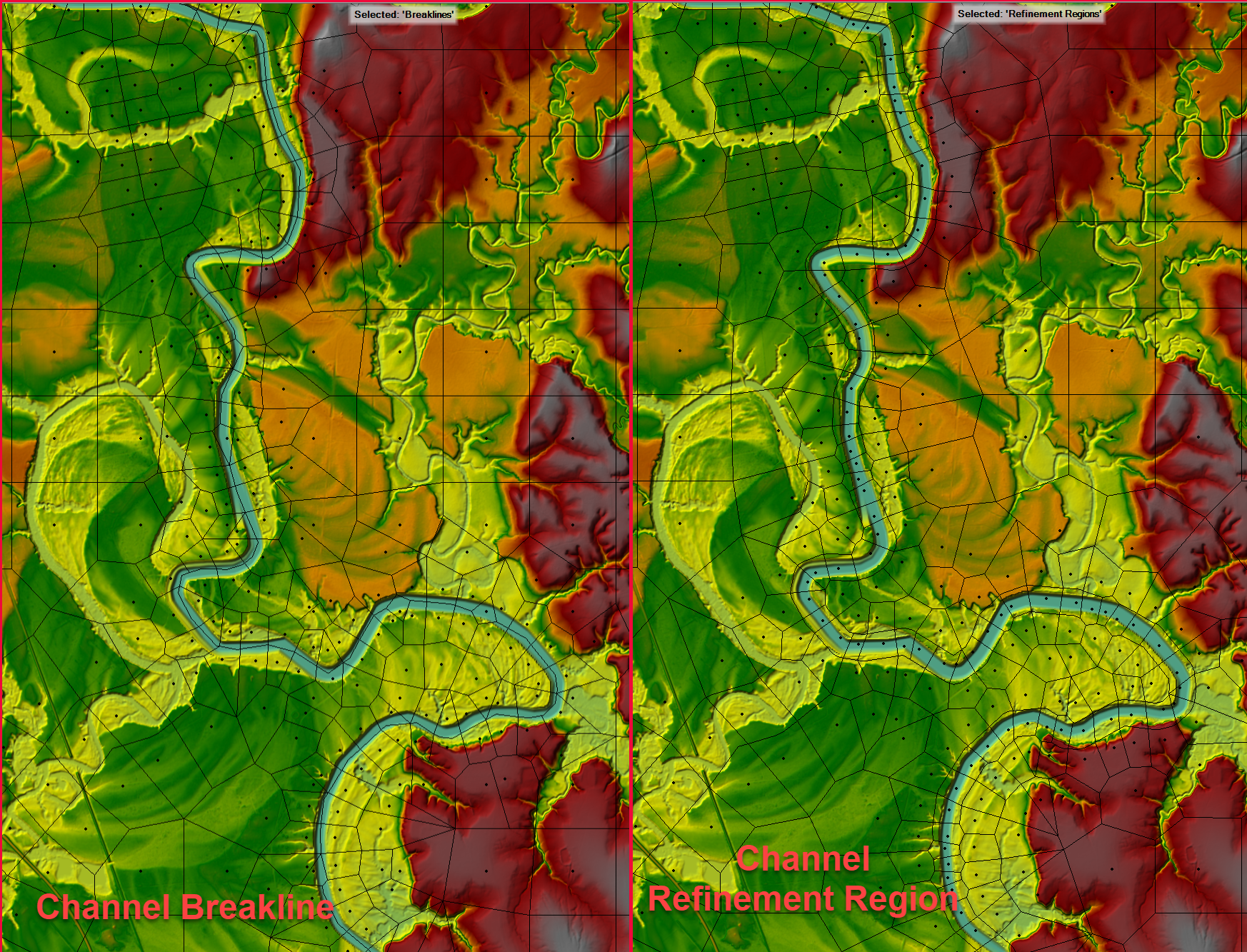
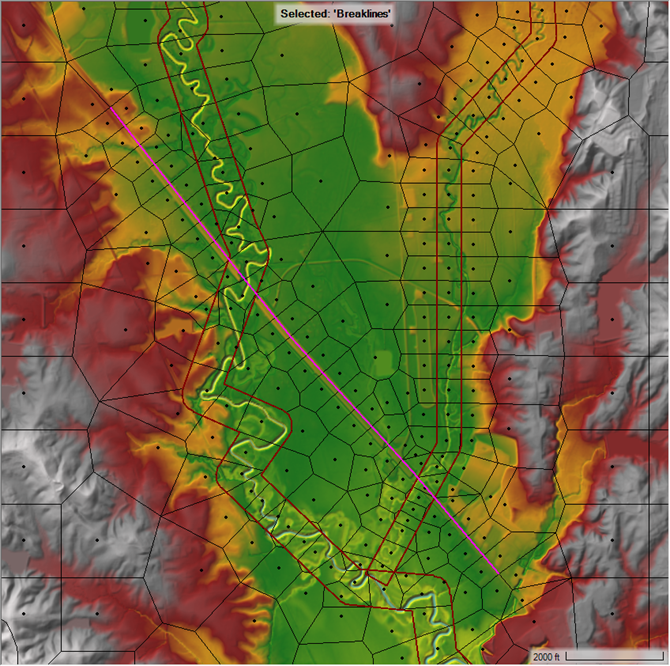
An alternative approach is to create Refinement Regions from channel flowlines, which often results in better cell alignment and placement for channels. For example, the image below compares using a Breakline and a Refinement Region for enforcing cell alignment along a sinuous channel. You can see that the Refinement Regions aligns cells nicely with flow direction and does a better job at following channel banks.
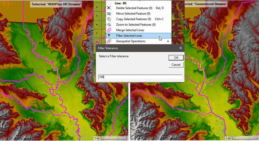
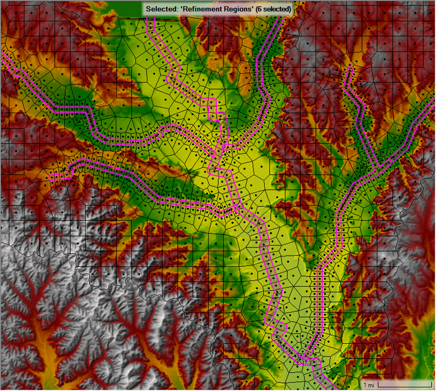
Fortunately, HEC-RAS Mapper makes generating Refinement Regions from flowlines easy. In RAS Mapper, select the flowline features (USGS NHDPlus HR Flowlines for this example) where you want to create Refinement Regions. If the channels are particularly sinuous or braided, right-click them and use the Filter Selected Lines option to generalize the polylines. This will make for more uniform Refinement Region shapes that are easier to enforce in the mesh.
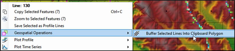
Right-click the filtered flowlines lines and choose the Buffer Selected Lines To Clipboard Polygon Geospatial Option option and select and appropriate width for the new polygon. Note the buffer width as you will use that for the cell size next. The resulting polygons are stored in the clipboard so you can right-click and paste them directly into the Refinement Region layer.
Once the polygons are pasted in the Refinement Region Layer, inspect them to ensure that they generally follow the bank lines well. In places where precisely following the banks is critical for hydraulic connectivity such as perched channels or adjacent levees, time should be to ensure the polygon boundaries capture those features. Once the polygons are pasted in the Refinement Region Layer, open the Refinement Region Editor and set each Refinement Region X and Y cell size to the buffer width you selected for the polygon.
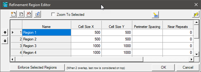
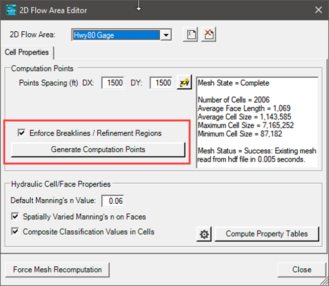
Then, Generate Computation Points for the mesh, enforcing all Breaklines and Refinement Region. Inspect the resulting mesh.
Collisions in the mesh generation process can result in less desirable cell placement to occur where the Refinement Regions meet at confluences, or where they overlap with Breaklines (representing other features like high ground or bridges crossing the channel). The figure below shows a confluence with a Breakline representing a bridge and overlapping Refinement Regions.
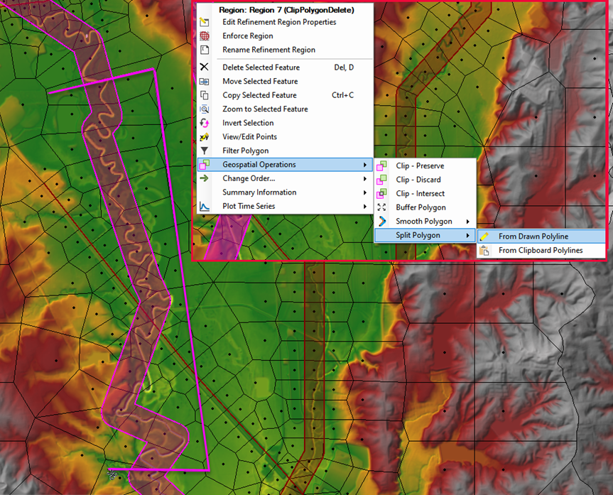
To resolve these collisions, the Refinement Regions can be trimmed just short of the confluences at the problematic locations. In RAS Mapper, right-click the Refinement Region and select the Split Polygon operation. Then, draw a polyline to split out the undesirable portion of the polygon and delete it like shown below.
After clipping the refinement regions around the bridges, cells are more orderly and better aligned around the confluence and bridge.