Download PDF
Download page Bridge Development.
Bridge Development
Data Files
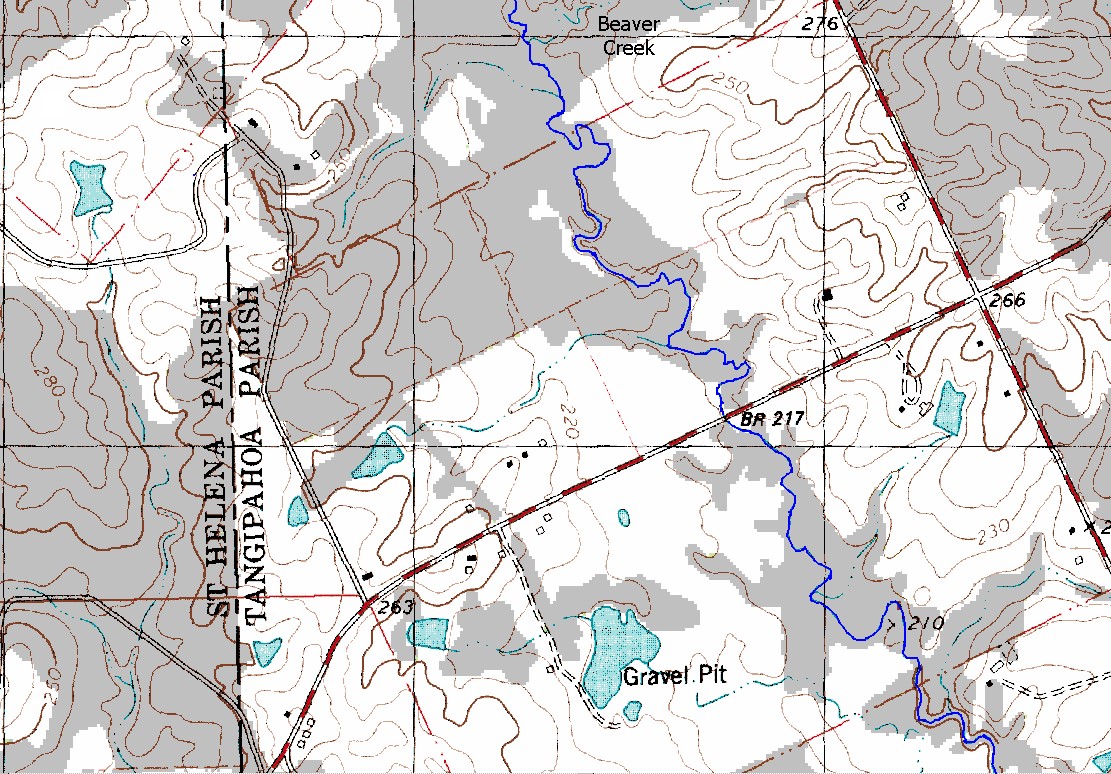
You will be working with a section of Beaver Creek located near Kentwood, Louisiana. The data for this tutorial is provided in the zip file.

Objective
This workshop will help students learn how to use HEC-RAS to enter and edit bridge data, place ineffective flow areas, and define a bridge modeling approach.
Background
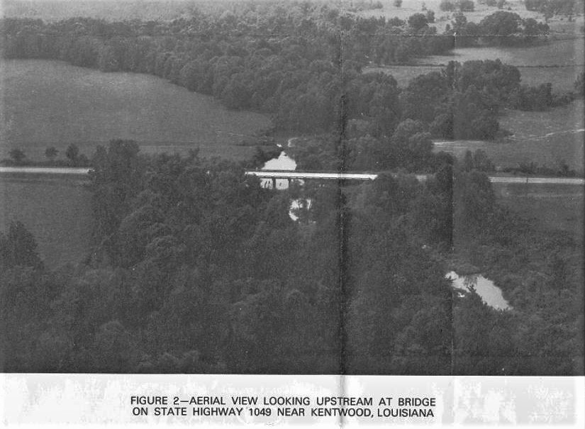
The stream for this example is a section of Beaver Creek located near Kentwood, Louisiana. The bridge crossing is located along State Highway 1049, near the middle of the river reach. The field data for this example was obtained from the USGS study “Backwater at Bridges and Densely Wooded Flood Plains, Beaver Creek Near Kentwood, Louisiana” by George J. Arcement, B.E. Colson, and C.O. Ming.
Enter Bridge Information
- Start HEC-RAS.
- Open the “BridgeDevWorkshop” dataset in the Bridge Development Workshop folder.
- Save a new geometry from the existing geometry, and name it “Bvr Crk Bridge-Energy”
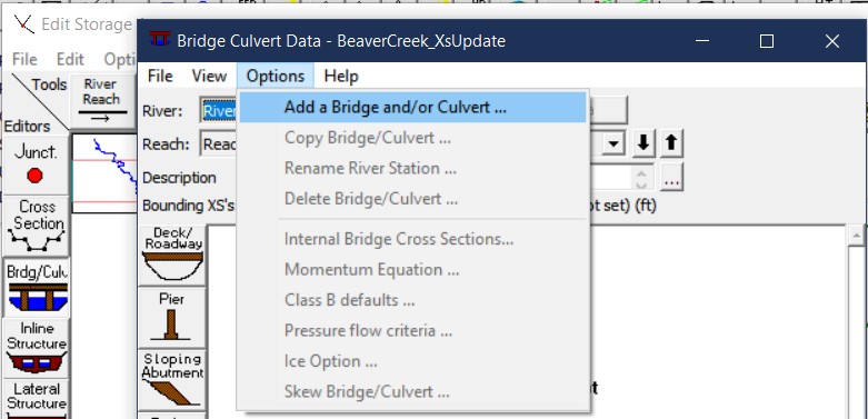
- Add a new Bridge at Station 5.4 from the Bridge/ Culvert Editor.
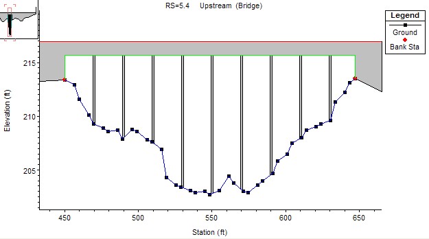
- Enter the bridge data based on the following information:
- Road embankment is at a constant elevation of 216.93ft.
- The bridge low chord is at elevation of 215.7 ft.
- The bridge opening has vertical walls at cross section stationing 450 ft and 647
- The bridge deck is 40 ft wide, and the upstream side of the bridge deck is 30 ft from the upstream cross-section. The upstream and downstream sides of the bridge are exactly the same.
- The bridge has 9 piers. The piers are 1.25 ft wide each and have a square nose. The piers are spaced 20 ft. apart on center, starting with the first pier at station 470 ft.
Enter the Ineffective Flow Area Data
- Starting with the bridge’s upstream cross-section (5.41), place simple ineffective areas to remove conveyance where the flow will be contracted.
- Assume a contraction ratio of 1:1 to determine the stationing of the ineffective flow areas.
- For the trigger elevation the top of the roadway is a decent place to start.
- Similarly, add ineffective flow areas to the downstream cross-section (5.39)
- Assume an expansion ratio of 2:1 to determine the stationing
- For the trigger elevation, the top of the bridge opening is a decent place to start.
- Finally, set appropriate expansion/contraction coefficients for cross-sections around the bridge.
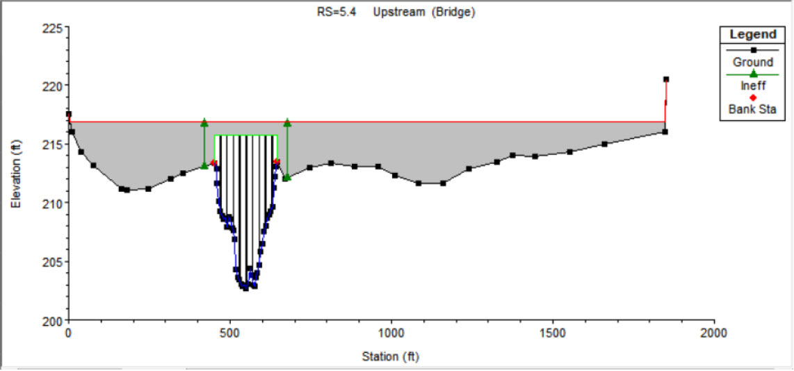
The expansion and contraction ratios (ER and CR) in the figure below were provided in the workshop as 2:1 and 1:1 respectively. This means that for every foot upstream of the bridge the flow area on each side of the channel will widen by a foot. The upstream cross-section is 30 feet from the bridge, so the ineffective flow areas on each side should be 30 ft wider than the bridge opening.
The downstream cross-section is also 30ft from the bridge, but since the expansion ratio is 2:1 the ineffective flow areas will only be 15 ft wider than the bridge opening.
If the ratios were not provided, the HEC-RAS Hydraulic Reference Manual contains a tables of ranges for both expansion and contraction ratios based channel slope and n values.
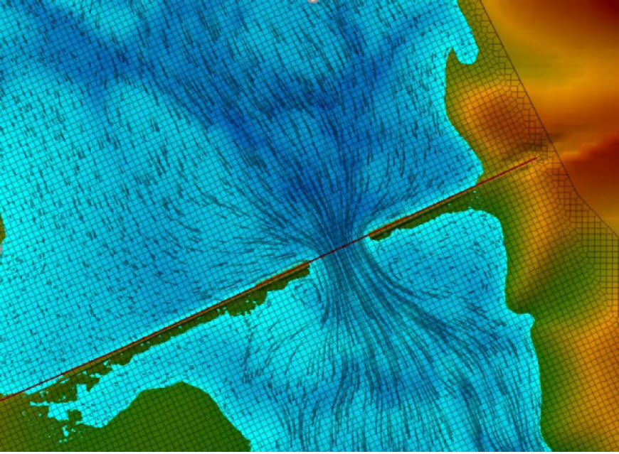
Another way to do this is to create and run a small 2D model through the bridge and use tracers to see how flow contracts and expands due to the constriction of the bridge as shown in the image below.
For a typical bridge section, the HEC-RAS Hydraulic Reference Manual suggests:
Contraction – 0.3
Expansion – 0.5
However, the embankment for this bridge blocks a good portion of the cross-sections rather abruptly, so a sensitivity analysis would help in determining which coefficients to are more appropriate.
Contraction begins at cross section 5.44, and expansion ends at 5.29, so the coefficients should at least be changed for 5.44, 5.41, and 5.39.
Set Bridge Modeling Approach
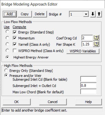
- Set the Bridge Modeling Approach for Low Flow to use the Highest Energy answer among the Energy, Momentum, and Yarnell solutions.
- Note, you will have to find the appropriate parameters for both the Yarnell and Momentum equations.
- Set the Bridge Modeling Approach for High Flow to use Energy Only
- Close the bridge editor and save the geometry.
- Create another new Geometry and switch the bridge High Flow Method to Pressure / Weir. Save the geometry as “Bvr Crk Bridge-PW”
- Set the fully submerged coefficient of discharge Cd to the typical 0.8.
The help buttons in the Bridge Modeling Approach Editor took me right to a helpful page int the Hydraulic Reference Manual that suggested Yarnell and Momentum parameters based on pier shape nose shape.
Momentum – 2.0
Yarnell – 1.25
The embankments block a significant amount of the cross-sections around the bridge, and the opening is relatively small compared to the embankments. That said, I would expect water to back up behind the bridge, submerge the inlet and possibly the outlet. Additionally, if the water surface elevation is high enough I’d anticipate substantial weir flow for the long embankments on either side of the bridge.
Create Steady Flow Plans
- Create Steady Flow Plans for each geometry using the existing flow file that has 3 flows for 5000, 10000, and 14000 cfs.
- Give the Plans appropriate Titles and Short IDs to indicate what high flow method is used.
- Compute each plan.
- Fix any geometry errors that are preventing the plans from running.
Congratulations, you have completed this workshop! In the next workshop you will analyze the results of each plan, determine which is the best bridge modeling approach, and make adjustments to improve the solution as needed.