Download PDF
Download page Copying Your Bridge Data into the FHWA Toolbox.
Copying Your Bridge Data into the FHWA Toolbox
In order to view bridge scour results in the toolbox you need to copy the bridge cross section and geometry into the hydraulic toolbox.
These steps walk you through that process, starting with a new Toolbox project and analysis.
Bridge Scour Export Tool Does this Step Automatically
If you are using the Bridge Scour Export tool in HEC-RAS (new in version 6.7Beta4) you should be able to skip most of this step.
The tool reads your bridge geometry and exports it to a Hydraulic Toolbox File (*.hyd) automatically.
1. Create a Bridge Scour Analysis in the Hydraulic Toolbox
Open the Hydraulic Toolbox and select File→New to create a new Project file in the toolbox (a *.hyd file).
Select File→Save As... and give it a name.
The click on the Project Folder in the Project Explorer and select the Bridge Scour button.
![]()
(You can also select Calculators→New Bridge Scour Analysis from the menus).
Then double click on the Bridge Scour Analysis node that appears in your Project Explorer.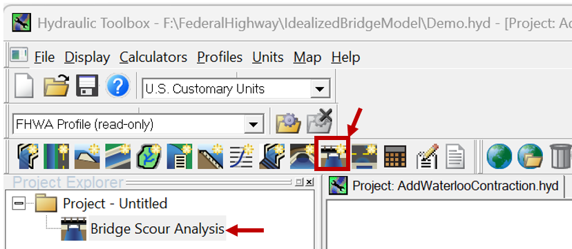
2. Expand Bridge Geometry Editors in the Toolbox
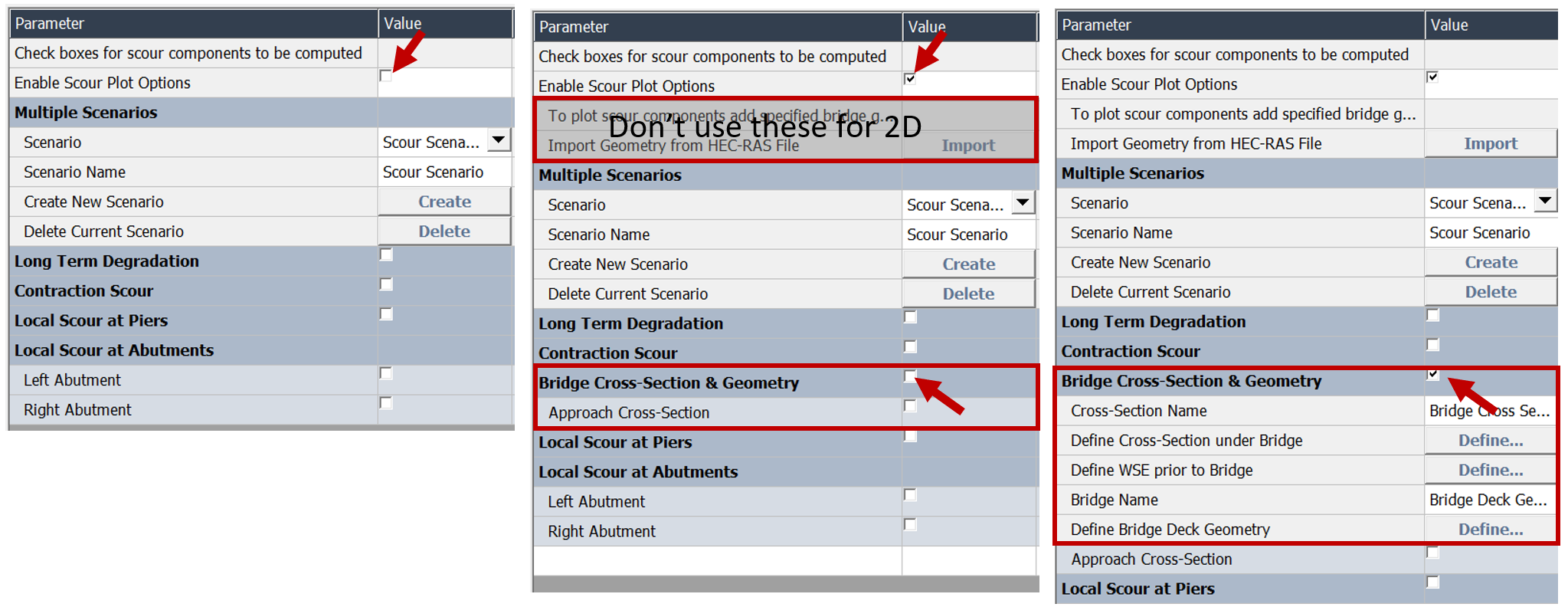
The bridge scour analysis interface (below-left) does not automatically open with the bridge geometry entry options.
To enter your cross sections click the small check box in the second row of the editor: Enable Scour Plot Options.
Enabling these options will add two new sections to the editor.
It adds two rows just below the check box that are for 1D modeling. Ignore those (see image below).
It also inserts two new rows between Contraction Scour and Local Scour at piers (e.g. Bridge Cross Sections & Geometry).
Select the check box next to Bridge Cross-Section & Geometry (see image below).
This check box will expand this geometry section of the editor to include five additional rows.
3. Copy the Bridge Cross Section into the Toolbox
Select your SA/2D Connection from the geometry node in RASMapper.
Then right click on the centerline of the bridge in mapper and choose PlotSA2D Conn Data

This will open the new Coordinated 2D Structure Plot.
You can get to the cross section data by pressing the Data Table button. 
Press Shift and select the Centerline Station and Elevation data.
Take note of the number of station-elevation points.
Then right click on the selected data and select Copy to copy these values.
Back in the Hydraulic Toolbox, select the Define  button in the Define Cross-Section under Bridge button.
Type the number of station-elevations points from the HEC-RAS cross section in the text box at the bottom of the editor.
Then paste the data in the editor (Ctrl+V or right click→ Paste) and press OK.
Back in the Main Editor, press Plot Preview to see the cross section.
If terrain piers show up in your cross section, remove them from your Hydraulic Toolbox XS
The Hydraulic Toolbox may plot results better if the copied RAS cross section includes the piers from terrain mods in the cross section.
HEC recomends including piers in the terrain, so you will have to do this manually in the Hydraulic Toolbox Editor.
3. Copy the Water Surface Elevation
If you run your simulation, the lateral water surface profiles for the headwater and tailwater will also show up in the Structure Coordinated Plot and the table.
Select the Station-Elevation data for the headwater (HW WS) and take note of how many station-water surface points there are.
(Note: many of these water surfaces will be relatively flat, and the station-water surface results will have more points than needed to define the line.
But there is no cost in just copying it over, and it will sometimes capture lateral stage effects.)
Press the Define button in the Define WSE Prior to Bridge row.
Specify the Number of x,y points:
Right click on the RAS Data to get the Copy menu.
Paste into the Hydraulic Toolbox Editor.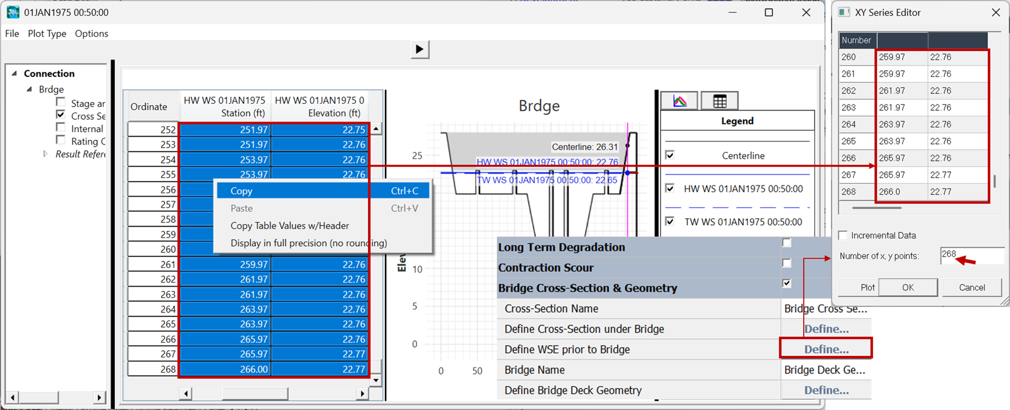
4. Copy the Bridge Geometry into the Toolbox
For the rest of the bridge geometry, close out of Mapper in HEC-RAS and open the Geometry File. ![]()
Then open the SA/2D Connection editor: 
(Note: In 2D, bridge data are not in the bridge editor because bridges are defined as 2D/SA Connections in a 2D simulation)

There are up to three bridge components you need to copy into the Hydraulic toolbox:
i. Bridge Deck
Press the Deck/Roadway button (see above) to access these data.
Open the Define Bridge Deck Geometry Editor in the Hydraulic Toolbox, by pressing the Define button.
Specify the number of rows in your bridge deck and paste the upstream values.
(Note: Only use the upstream values, there is no need or mechanism to specify the downstream values).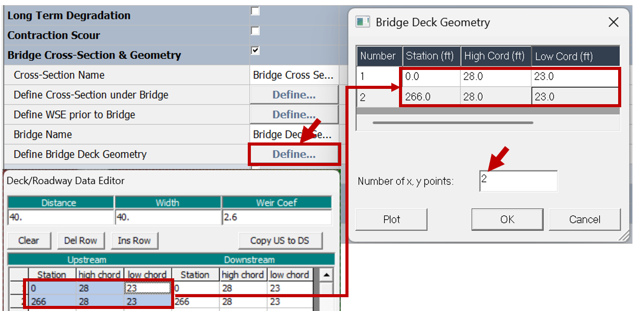
ii. Piers
In HEC-RAS, select the Pier button on the 2D/SA Conn editor to access the pier data. ![]()
Piers are defined under a different section in the Hydraulic Toolbox.
Click the Local Scour at Piers check box to expand this section.
The press the Define button to launch the Pier Geometry editor.
Entering All Pier Data Together Can Save Time
Since many piers have similar geometries and use the same hydraulic parameters for scour, it can be efficient to enter the pier geometry and the pier scour parameters together for the first pier and then duplicate and update each one in turn.
Copy the Pier Width-Elevation information from HEC-RAS to the Toolbox Pier Geometry Editor.
Then transfer the centerline of the stream on the Centerline Station of Pier row of the toolbox.
Finally, leave the Pier Scour Refernce Point as Thalweg.
(We will explain this in more detail under the Pier Scour discussion).
Then duplicate your pier.
If your elevation-width data are consistent across your piers then you will only need to update the centerline.
Scroll through the HEC-RAS piers to find the new centerlines.
iii. Abutments
Enter the abutment data in the Local Scour at Abutment section of the hydraulic toolbox.
Click the check box next to the abutment you would like to enter (e.g. Left Abutment).
Press the Define button to copy abutment data.
Copy the upstream face abutment data into the Hydraulic Toolbox Editor.
Repeat the process for the HEC-RAS abutment 2 and the toolbox Right Abutment.
Press Plot Preview at the bottom of the editor to see the bridge you entered.