Download PDF
Download page Extracting Contraction Scour Variables from 2D HEC-RAS.
Extracting Contraction Scour Variables from 2D HEC-RAS
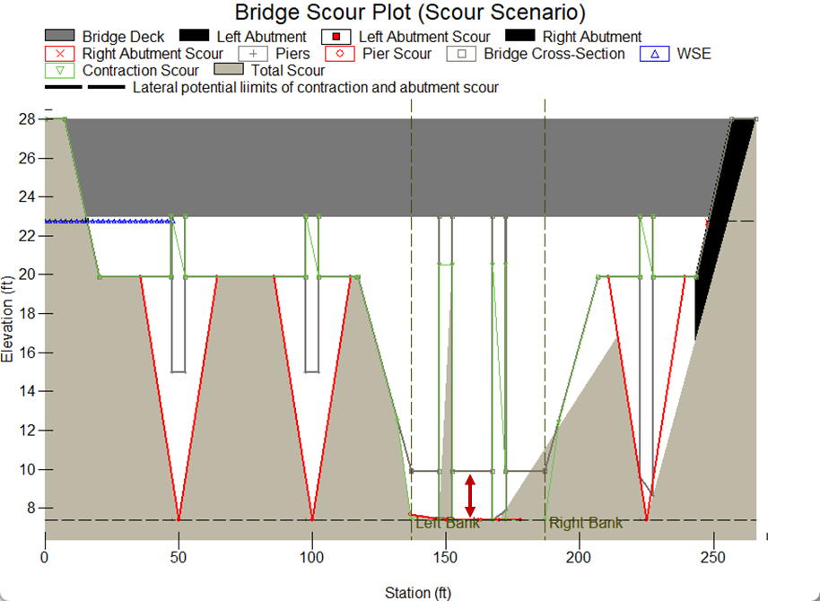
A bridge induces contraction scour when the bridge reduces the cross-sectional area of the river ("contracting" the flow). The river must push the same flow through a smaller area (Q=VA) which causes the water to accelerate through the bridge. This contraction increases the river's potential to pick up and transport sediment through the bridge. A bridge contraction is often lateral as the width of the river decreases through the bridge. But if the flow increases to engage the low chord of the bridge (i.e. the bottom of the bridge deck) the bridge can also contract flow vertically, inducing pressure flow. HEC-18 treats contraction scour differently with and without pressure flow. This section is just for low-flow (no pressure/orertopping).
Access the Bridge Scour Hydraulic Data from HEC-RAS
To access the bridge scour variables from the reference lines you laid out right click on the top-level result node and select Show Result Table. ![]()
You can also navigate to the reference line in the Result Geometry (not the geometry portion of the Mapper tree) and right click on a Reference line.
(Note: You will only get results if you have run the simulation. Reference line data are populated at runtime.)
The results available in this table are the variables required for bridge scour analyses:

2. Contraction Scour (Channel)
i. Clear Water/Live Bed
The contraction scour equations have two modes:
- Clear Water: The clear water mode assumes that the channel hydraulics upstream of the bridge do not mobilize bed material, so the water entering the bridge is not transporting any bed load. Clear water scour only requires input parameters (Flow, Width, Depth) from the contraction cross section (Bridge). If your bridge is in the clear water regime, it does not need information from the approach cross section (except to determine the regime).
- Live Bed: If the velocity in the channel is higher than the computed "critical velocity" required to move the bed material, the HEC-18 equations assume that the channel is carrying bed load. If your bridge is in the live bed regime, it needs more input data. The live bed equations assume that bed load causes vertical purturbations in the bed elevation (e.g. bedforms passing or stochastic fluctuations around a mobile bed). Therefore, live bed results account for the deepest trough of the mobile bed condition and are more conservative (larger scour dephs).
(Note: This bedload sensitivity of the clear water/live bed decision is why the "channel" is actually the movable bed of the channel, the portion of the river that transports bed load).
Therefore, when you open the Contraction Scour editor in the Hydraulic toolbox, it only shows three editable variables (Avg Approach Depth, d50 and Avg Approach Velocity).
It uses these to determine the clear water/live bed mode, and then populates all of the other input and output.
(Note: The toolbox still gives you all of the input and output required for both methods after it determines which method it will use, so it will include some data you do not need for the method it selected).
Click on the check box next to Contraction Scour in the toolbox.
Ignore the Left and Right Contractions for now, we fill those out below.
Press the Define button on the Define Contraction Scour Parameters row.
This will launch the editor with just the three clear water/live bed inputs.
For this part of the calculation, you only need two results from the Approach Channel Reference Line:
- Average Velocity (Velocity in HEC-RAS) and the
- Average Depth (Hydraulic Depth in HEC-RAS)
- You also need to define the median particle size from the surface sediment in the channel at the approach cross section (in mm, even if the rest of your input data are in US Customary)
The input data in the toolbox and where they come from in the HEC-RAS output are illustrated below.

ii. Channel Contraction Scour Data
The figure below maps the HEC-RAS data to the appropriate input rows in the toolbox.
All data either comes from the approach or contraction channel reference lines.
Ignore the pier approach reference lines as well as the left and right overbanks.
Only use the velocity and hydraulic depth (not Depth Max or Velocity Max - those are fore piers).
If you need more significant figures than displayed, copy the result and paste it in the toolbox.
The contraction width results from HEC-RAS should exclude the pier width
(In the example below the results reduce the contraction width automatically because the piers are in the terrain)

All data requirements for both scour regimes will populate once the toolbox selects a regime.
When you compete all the data for the selected regime, the model will compute a scour depth.
Negative scour depths translate to no scour.
iii. Overriding the Scour Regime
The toolbox computes both Clear Water and Live Bed Scour but reports and plots the "Recommended Scour Condition" based on the critical velocity.
But it also reports the critical velocity so you can evaluate your result.
The example below identified the Clear Water regime but the computed velocity (2.02 ft/s) was only 0.04 ft/s less than the critical velocity (1.98 ft/s).
This result is functionally at critical velocity and (given the uncertainties of the analysis) could be Clear Water or Live Bed.
The live bed equations (2.5ft) computed more scour than live bed (1.7ft).
Therefore, since the decision criteria (V~Vc) could easily go either way, the interface allows users to override the clear water condition with Live Bed and plot the more conservative live bed scour depth.

3. Contraction Scour - Overbanks

