Download PDF
Download page Dam Breach - Simple 2D Geometry.
Dam Breach - Simple 2D Geometry
Data Files
The data for this tutorial is provided in the zip file.

Objective
In this workshop, you will learn how to create an HEC-RAS model from a digital terrain model (DTM). The general process will teach you how to create geospatial data in RAS Mapper to represent the river system and floodplain area specifically for performing a dam breach analysis with HEC-RAS. Once the geometric data has been created, you will identify data that requires correction and enter remaining data to complete the RAS model.
Background
You will be working on Bald Eagle Creek near Lock Haven, PA. A flow hydrograph will be used to simulate inflows to into the reservoir behind Sayer's Dam. The water surfaces will then be used in the GIS to perform floodplain mapping.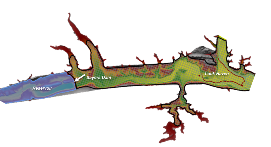
This workshop is comprised of two parts: geometric data development using HEC-RAS Mapper; and completion of the data in the HEC-RAS Geometric Editor.
Work quickly, but thoughtfully, and be sure to read each part carefully. When you have questions, don't hesitate to ask! Lastly, don't get too carried away with being accurate – this is a workshop. It is intended to highlight the general use of using HEC-RAS Mapper for data development and editing.
Start a new HEC-RAS Project with Terrain
You will be starting from scratch with a new HEC-RAS project.
Create a new HEC-RAS Project
- Create a NEW HEC-RAS project and give it a Name.
- Go to the Geometric Data Editor and select File | New Geometry Data.Provide a name and press OK.
Import the Terrain Model
- Open RAS Mapper and set the Projection for the project, using the Tools | Set Projection for Project menu item. Browse to the "GISData" folder in the workshop folder and select the "projection.prj" file.

- Create a new terrain model using the Tools | New Terrain menu item.
- Click to + button to add the terrain file. Use the "BEC.tif" file located in the "GISData" folder.
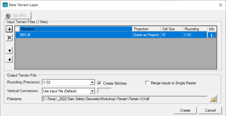
- Press the Create button to import the terrain data.
- Close the dialog once the Terrain has been created.
Geometry Development
Use the RAS Mapper Editing Tools to create a 1D RAS model geometry. Pay attention to using the correct tool to Add New ![]() versus Select / Edit
versus Select / Edit ![]() on the selected layer. Open the Geometry for Editing
on the selected layer. Open the Geometry for Editing
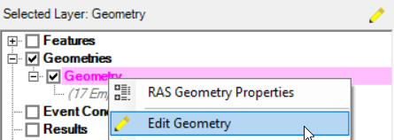
- Open RAS Mapper.
- In RAS Mapper, Select the new Geometry layer, right-click and choose "Edit Geometry" or click the Edit button (Pencil).
Create the Storage Area for the Reservoir
- Click on the Storage Areas layer.
- Draw a polygon representing the reservoir (you don't have to be precise).
- Provide a Name.
- The Elevation-Volume relationship will be automatically extracted from the terrain.
- You can plot the Elevation-Volume relationship for the polygon but right-clicking on the polygon and choosing Plot Elevation-Volume Curve.
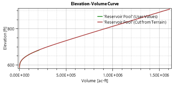
*Typically, you would want to override the Elevation-Volume relationship with pre-dam survey information, as most likely, the terrain in the reservoir pool is not correct.
Create the 2D Flow Area Downstream of Sayers Dam
- Expand the 2D Flow Areas layer to see sub layers.
- Click on the Perimeters layer
- Draw a polygon representing the area downstream from the dam downstream past Lock Haven.
- From the 2D Flow Area Editor…
- Set the Manning's n value for the 2D Area to 0.06.
- Generate Computation Points at a 500ft spacing

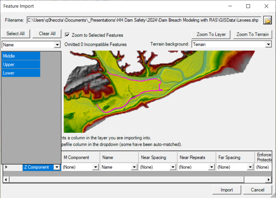
- Create Breaklines along the levees by importing them from shapefile
- Expand the 2D Flow Areas node
- Right-click on the Breaklines layer and choose Import Features
- Select the
- Import the Levee shapefile for the upper, middle, and lower levee to the Breaklines layer.
- Right-click on the Breaklines layer and choose Enforce All Breaklines to modify the mesh.
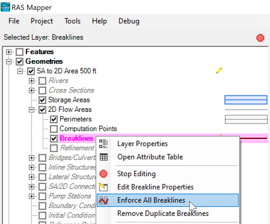
The mesh should look similar to the figure below.
Create the Additional Breaklines (as appropriate)
- Select the Breakline layer
- Create additional breaklines where appropriate to align cell faces!Note: looks for roads and other high ground that directs flow.
- Enforce all breaklines (make sure the mesh computes)
Create Boundary Conditions
- Click on the Boundary Conditions Lines layer.
- Navigate to the most downstream end of the 2D Area and create a BC Line at the end of the 2D area on the outside of the 2D Area.
- Provide a Name.
Create a SA/2D Connection for the Dam
- Click on the SA/2D Connections structure layer
- Layout the Inline Stucture (left to right when looking downstream).
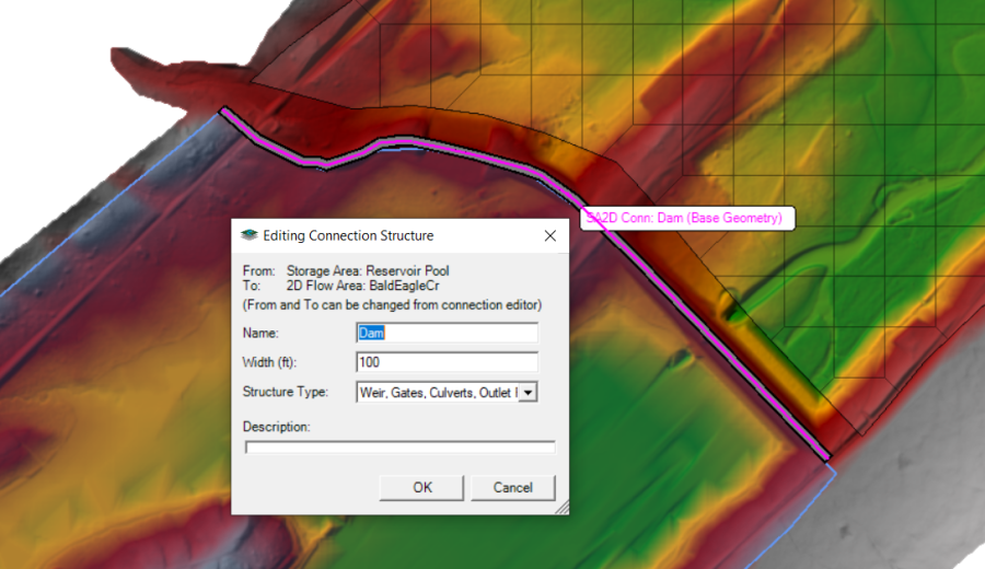
*You may need to override the weir profile for the Structure from the SA/2D Connection editor in the Geometric Editor. Breach information is also accessed from the SA/2D Connection editor.
Manning's n Values - We are skipping the detail version of this today.
Compute Hydraulic Property Tables
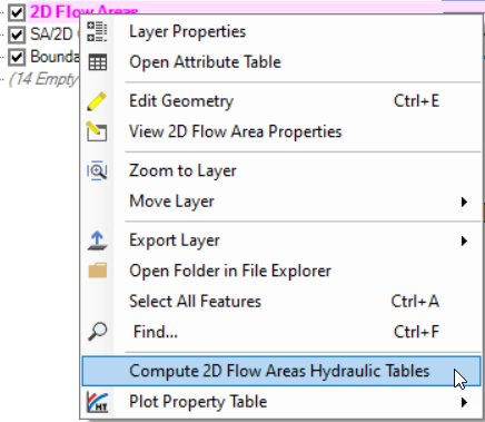
- Click on the 2D Flow Areas layer
- Right-click on the 2D Flow Areas layer and choose the Compute 2D Flow Areas Hydraulc Tables menu item
Stop Editing
- When FINISHED created features, select the Geometries Node | Stop Editing menu item.
- Close RAS Mapper.
Finish Entering Geometric Data
If you haven't already, close RAS Mapper and open the Geometric Schematic. Your geometry will not be loaded automatically.
- Open the geometry you created using RAS Mapper using the File | Open Geometry menu item.


Storage Areas
- Select the Elevation versus Volume Curve method for the storage areas and verify the data.
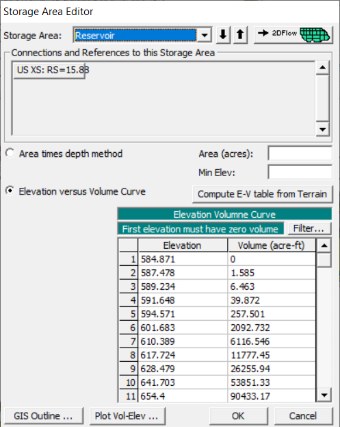
- You may also want to filter the points or replace with survey data.
SA/2D Connection Structure
- Open the SA/2D Connection Structure editor.

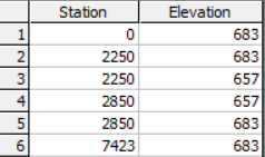
- Override the Weir information.
- Dam Crest @ 683 ft.
- 500-ft wide Auxiliary Spillway @ 657 ft (on the left embankment)
- Provide a Weir coefficient of 2.6 for the auxiliary spillway.
- Add a low-level outlet - locate it in the channel.
- Invert Elevation @ 590 ft.
- Use a circular culvert with 2 ft diameter.
Bonus
If you have time, create an unsteady flow simulation and try to run the model. This will allow you to see if the geometry has been input properly!
Flow Data
After you have created the Geometry, add flow data to the RAS project.
- Open the Unsteady Flow data editor
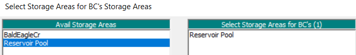
- Choose the Add SA/2D Flow Area button

- Add the Reservoir Storage Area Boundary Condition location
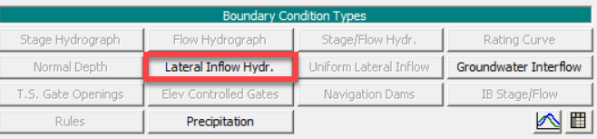
- Add the Lateral Inflow Hydrograph boundary condition
- Enter a Lateral Flow Hydrograph for the Reservoir.
- Enter a time series of data
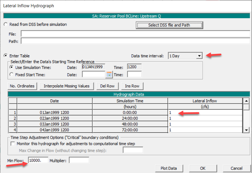
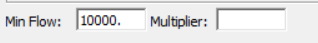
- Put in a Min Flow of 10,000 cfs for a steady profile.
- Enter a time series of data
- Enter a Normal Depth boundary condition with a slope, S=0.0004.
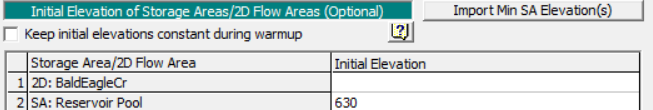
- Set the Reservoir Storage Area Initial Conditions to an appropriate Elevation from the Initial Conditions tab
- Save the flow data.
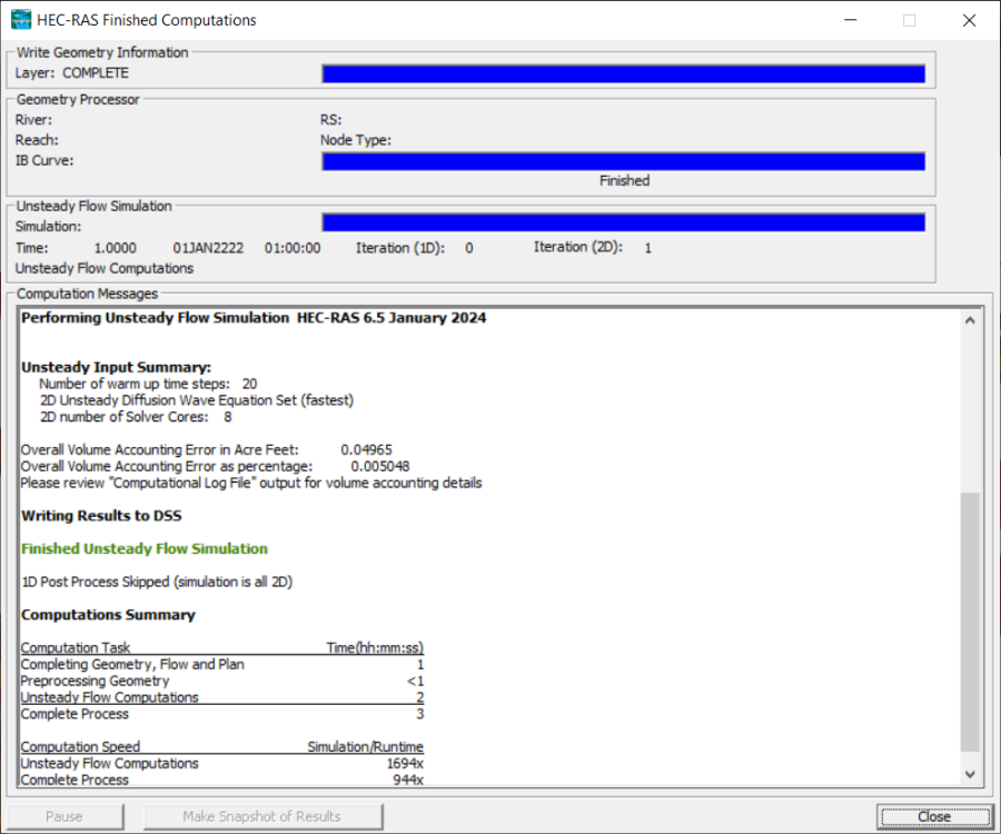
Simulate
Run the steady-flow simulation.
- Open the Unsteady Flow simulation dialog.
- Create a new Plan with a name and Short ID.
- Set the Simulation Time Window to run for an hour.
- Set the Computation Interval to 1min
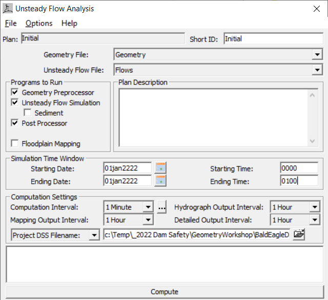
- Compute a water surface.
HEC-RAS will provide warnings if the data are incomplete. Read the error messages and work through data deficiencies.
If the simulation runs, it means you successfully satisfied the data development requirements and flow data entry.