Download PDF
Download page Floodway Encroachment Analysis (2D).
Floodway Encroachment Analysis (2D)
This tutorial demonstrates the approach to performing Floodway Encroachment Analysis for a simple 2D HEC-RAS example application.
This feature was introduced in HEC-RAS Version 6.4. This example has been created with HEC-RAS Version 6.6.

Overview
HEC-RAS is the primary river hydraulics software used to perform Floodway Encroachment Analysis for FEMA. Floodway encroachment analysis is used to determine guidelines for allowable development withing the floodplain fringe. FEMA guidance dictates that the model analysis be performed using the 100-yr floodplain and limits development within the the floodplain based on the impact to the computed water surface profile. Historically, this capability in HEC-RAS was limited to 1D Steady Flow and 1D Unsteady Flow analysis.
This example utilizes a simple 2D model developed for a study area intended to demonstrate typical modeling issues. Terrain data used in this model was downloaded from the USGS NED and has been resampled.
This example will take you through the procedure outlined below.
- Create a Calibrated model. This step is not performed in the example - you will be starting with a completed model.
- This model uses a single Manning's n value for the entire model domain. A good model would use appropriate Manning's n values throughout the modeling domain.
- This model uses the Diffusion Wave equation set. All models should be run with the Shallow Water Equation solution to identify if it is needed.
- Save the Base plan to an Encroached plan.
- Enter Encroachment data.
- Perform the Encroached run.
- Analyze the results.
- Refine the encroachment data.
- Perform final model simulation using Encroachment Regions.
Steps
- Open the HEC-RAS project "2DDWEncrExample.prj"
Prior to beginning a Floodway Encroachment Analysis, the river hydraulics model should be calibrated to and validated with observed data. The downstream boundary condition for the model should utilize the Normal Depth boundary condition (or rating curve) as it will allow for a changed stage as the flow hydrograph changes due to the encroachment. The model developed for this floodplain will be referred to herein as the Base Plan.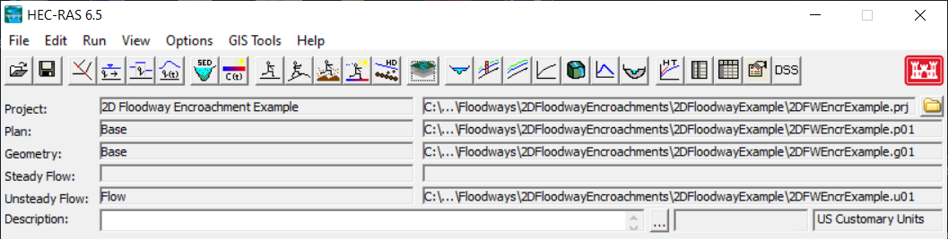
- Run the Base Plan
- Open the Unsteady Flow Analysis Dialog

- Compute the Base plan.
- Open the Unsteady Flow Analysis Dialog
- Add a Longitudinal Reference Line to the Base Geometry
A longitudinal line should follow the river channel of the river system. This will be used to evaluate the water surface profile results and to create Transverse Reference Lines.- Open RAS Mapper
- Start Editing the Reference Lines layer
- Create the River Line (from upstream to downstream) using the Add New tool.
- Name it "River".
- Add Transverse Reference Lines to the Base Geometry
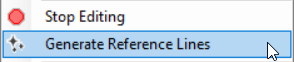
Transverse reference lines will be used to evaluate water surface elevations and velocities at various locations along the river.- Right-click on the Reference Lines layer and choose Generate Reference Lines
- Select the Base Result to evaluate
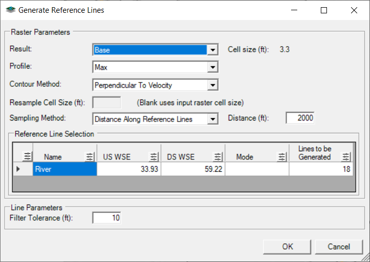
- Select the Profile to evaluate - Selecting a specific timeline is important for generating contours of velocity (Max will most likely be okay for stable models where flow does not reverse).
- Select the Perpendicular to Velocity Contour Method
- Select the Distance Along Reference Line Sampling Method
This method will create a Reference Line based on the distance specified. - Enter a sampling interval - 2000ft (or so)
- Select the Reference Lines to sample along
(You can select multiple Longitudinal lines to sample along if you have multiple rivers) - After the lines are created, Edit the lines to smooth them out and to make sure they cover the entire floodplain.
The automation tools are great, but they are not perfect. You will need to filter, lengthen, and move the lines to meet your needs
Creating reference lines can be created using automation tools or manually. There is also an interactive tool that will assist in creating lines by tracking velocity at a point.
- Right-click on the Reference Lines layer and choose Generate Reference Lines
- Open the Unsteady Flow Analysis Dialog and re-Compute the Base plan
Copy the Base plan using the File | Save Plan As menu item on the Unsteady Flow Analysis dialog.
Provide a new name for the encroached plan and hit okay, in the dialog. Provide a ShortID for the new plan.
The Encroached plan must utilize the identical geometry as the Base plan.
- Add the Depth*Velocity layer for the Base plan.
- Right-click on the Base plan
- Choose the Create New Results Map layer menu item.
- Expand the Hydraulics variables list
- Select the Depth*Velocity variable
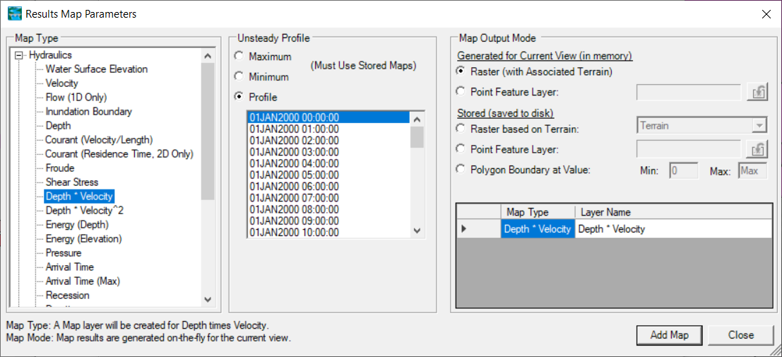
- Press the Add Map button
- Close the Results Map Parameters
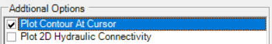
- Double-click the DV Layer and turn on the Plot Contour at Cursor
- Animate the DV layer to the timestamp of interest (02JAN2000 0100).
- Investigate – then identify a DV Contour Value you want to use as a first cut at defining the floodway boundary – you will use this in a later step when we create the initial floodway Encroachment Regions.
For this example, we are assuming that the water surface profile and DV Contour Value for the entire model domain is acceptable. This may be not be acceptable for very long river hydraulic models, where the peak floodwave is not at all locations of the model at the same time step or where a DV Value changes based on hydraulic conditions (river slope). If the model domain is significantly large, you will have to generate individual polygons (Zones) for separate regions of the model.
- Generate Floodway Encroachment Polygons
- Expand the Plans group and the Floodway plan
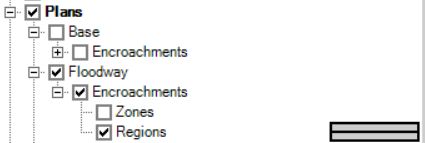
- Select the Encroachment Regions layer and Start Editing the Encroachment Regions Layer.
- Generate a preliminary Encroachment Regions polygon by selecting the Generate Floodway Encroachment Polygons | From Map Results menu item from the Encroachment Regions layer.

- The following dialog will appear. Enter information.

- Select the Base plan.
- Select the DV Map layer (you will need to have pre-selected the profile of interest).
- Provide a Resample Cell Size.
Resampling the map will speed up computations! - Enter Contour information into the Generate Floodway Encroachment Polygons wizard
Note that the larger the Contour Value the smaller the effective floodway.
If you are using Zones (you will need to create zone polygons in the Zones layer), you can override the contour values. - Provide a Filter Tolerance.
- Provide a Simplify Tolerance.
- Press OK to create the polygons
- Expand the Plans group and the Floodway plan
- Perform initial Edits to the floodway encroachment region polygons. There are many editing options available.
The Encroachment Regions should be modified at (1) all boundary conditions to make sure then go completely to the edge of the 2D Mesh, (2) the floodway boundary to smoothly transition throughout the floodplain, (3) major tributaries that should be included in the floodway encroachment analysis.
- Start Editing the Encroachment Regions layer
- Once done editing... Stop and Save Edits
- Close RAS Mapper.
- Open the Floodway Plan
- Open the Floodway editor from the Options | Unsteady Encroachments menu item

- Select the Base plan
- Enter the Target WSE Rise
- Enter the Fill Slope for the Encroachment Terrain Modification (0.001)
- Enter the Additional Fill for the Encroachment Terrain Modification (0.0)
Adding additional fill may be necessary if the Terrain Modification fill method doesn't correctly fill the floodplain.
- Press OK to close the editor

- Save the plan
- Compute
- A new RAS Terrain will be added to RAS Mapper. The new RAS Terrain (named "Terrain.Floodway.Encr") will be modified and used for developing Hydraulic Property tables and for floodplain mapping.
- Before the model simulation (a) Terrain Modifications will be used to raise the terrain based on the user-defined encroachment boundaries and Target Rise and (b) then used to update the Hydraulic Property tables for each cell in the 2D Mesh. The terrain will be raised to the target water surface elevation (specified for the Unsteady Encroachment run) along the floodway boundary and slope upwards to the higher elevation away from the boundary. (This process filling the terrain to a higher elevation may fail in highly 2D areas. Adding Addition Fill is often helpful.)
- After the model simulation the modified Terrain model will then be used for floodplain mapping.
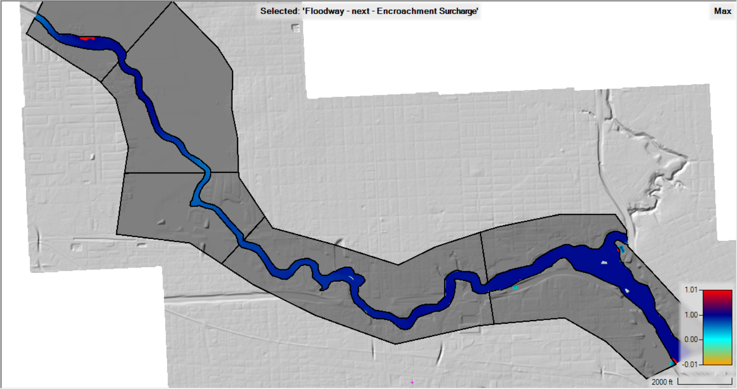
- Evaluate the results - most likely you will want to improve the Encroachment Regions - using the Encroachment Surcharge map. Below in an example plot of the encroachement surcharge map for this example.
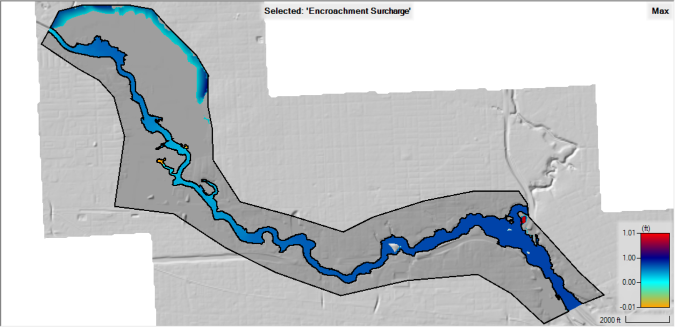
Note that flow is immediately breaking out into the North side of the river at the upstream end. The is example is intended to highlight two important modeling considerations. (1) When performing 2D modeling, choose the study reach carefully such that flow is predominately one-dimensional at the boundaries. For this example, flow is two-dimensional at the upstream boundary, making for a poor boundary condition. (2) When HEC-RAS auto-generated Encroachment Regions it did not extend all the way out the edges of the 2D Mesh and you may need to manually edit the polygons at the upstream boundary.
- Edit the Encroachments | Regions layer using the Encroachment Surcharge map to inform your decisions.
- The upstream boundary may require editing.
- Improve the floodway by smoothing the boundary to satisfy the encroachment criteria.
- Break the regions at tributaries where significant flow is contributing to the system.
- Create additional/new Reference Lines to evaluate the floodplain (there are Reference Lines already provided for you in the base geometry).
- If you added new Reference Lines, you will need to re-run the Base plan.
- Re-run the Floodway plan.
- Plot the WSE and compare the results in RAS Mapper by right-clicking on the Floodway plan and choosing the Plot Results Profile menu item

- Profile Plot
The Profile Plot is accessed by choosing the Encroachment Plan and choosing the Plot Results Profile menu item. The Profile Plot shows a comparison of the Base and Encroached water surface profile as well as the difference between the two plots.- The Longitudinal Profile Plot is useful for quickly identifying where the Target Rise conditions are not satisfied and requires further refinement.
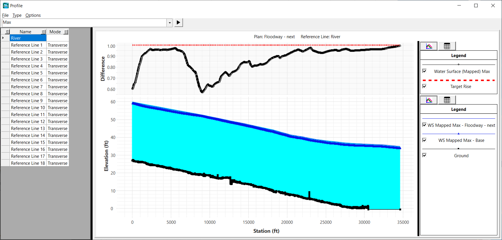
- The Transverse Profile Plot is useful for seeing the results at specific locations. Default plotting is for the Flow-Weighted Average Water Surface for the base and encroached plans.

- The Longitudinal Profile Plot is useful for quickly identifying where the Target Rise conditions are not satisfied and requires further refinement.
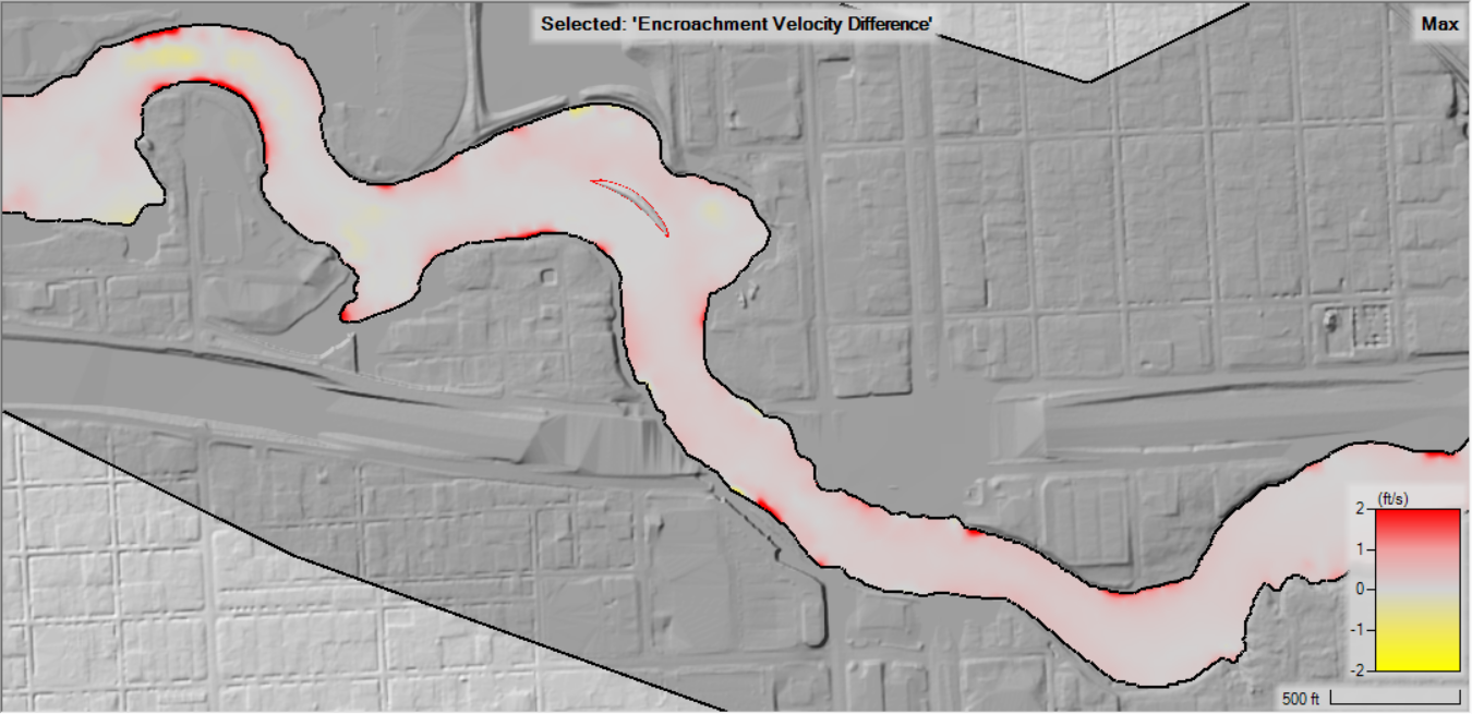
- Encroachment Velocity map - make sure that velocities have not changed significantly in within the floodway.
- Continue to refine the encroachment polygons in RAS Mapper as desired and re-compute the floodway analysis. The final floodway should meet the Target Rise criteria and produce a smoothly transitioning floodway boundary.