Download PDF
Download page Floodway Encroachment Analysis using Zones.
Floodway Encroachment Analysis using Zones
This tutorial demonstrates the approach to performing Floodway Encroachment Analysis for a simple 2D HEC-RAS example application (HEC-RAS version 6.6).

Overview
HEC-RAS is the primary river hydraulics software used to perform Floodway Encroachment Analysis for FEMA. Floodway encroachment analysis is used to determine guidelines for allowable development within the floodplain fringe. FEMA guidance dictates that the model analysis be performed using the 100-yr floodplain and limits development within the the floodplain based on the impact to the computed water surface profile.
This example utilizes a simple 2D model developed for a study area intended to demonstrate typical modeling issues. Terrain data used in this model was downloaded from the USGS NED and has been resampled.
Specific to this river example, the river is long enough and the hydrograph duration is short enough, that the peak stage does not occur at the same time throughout the system. Therefore, this example will demonstrate how to generate encroachment polygons with the Zones option.
This model is not intended to be used to make floodplain management or engineering decisions, but simply to demonstrate the procedure for performing an encroachment analysis with a 2D model.
This model is not complete. The flow data do not represent a true flow event. Channel data are missing. Manning's n value data are not well defined. Bridges are not included. The 2D mesh should be further refined. The model boundary near the downstream in not complete.
This example will take you through the procedure outlined below.
- Create a Calibrated model. This step is not performed in the example - you will be starting with a "completed" model.
- This model uses spatially distributed Manning's n values. They are not calibrated to observed data.
- This model uses the Diffusion Wave equation set. All models should be run with the Shallow Water Equation solution to identify if it is needed.
- Run the Base plan
- Create Reference Lines
- Save the Base plan to an Encroached plan.
- Enter data into the Encroachment Table.
- Perform the Encroached run.
- Analyze the results.
- Refine the encroachment data.
- Perform final model simulation using Encroachment Regions.
Steps
Open the RAS Project and Evaluate
- Open the HEC-RAS project "Example2DFloodway.prj"
Prior to beginning a Floodway Encroachment Analysis, the river hydraulics model should be calibrated to and validated with observed data. The downstream boundary condition for the model should utilize the Normal Depth boundary condition (or rating curve) as it will allow for a changed stage as the flow hydrograph changes due to the encroachment. The model developed for this floodplain will be referred to herein as the Base Plan.
- Run the Base Plan
- Open the Unsteady Flow Analysis Dialog

- Compute the Base plan
The Base plan uses the water surface from a previous run named "Initial". If this output file does not exist, your model won't run.
If the output file in missing, you can choose the "Enter Initial Flow..." option.
- Open the Unsteady Flow Analysis Dialog
- Open RAS Mapper

- Turn on the Velocity map
- Use the Animation bar to evaluate the floodplain
- Decide where you want to evaluate the floodplain with Reference Lines
Reference Lines are best suited to evaluate the floodplain in locations where flow is highly one-dimensional. An average water surface will be computed by HEC-RAS at reference line locations.
Create Reference Lines
Reference lines are used to evaluate results from HEC-RAS results. It is best to create them in locations where flow is 1D.
- Start Editing the Reference Lines layer
- Copy/paste the River feature from the Profile Lines layer (Profile Lines is under the Features group)
This line will be use to get a Profile Plot for the river system. - Create Reference Lines manually across the floodplain, as desired.
(Or use the automated tool described in the next steps.) - Turn on the Velocity map
- Double-click on the Velocity map to bring up the Layer Properties
- Turn on the Track Transverse Velocity at Cursor Plot Option

- Close the Properties dialog
- Zoom in to an area to place a reference line
- Use the cursor to create a Reference Line using the right-click at the location of interest and choosing the Velocity Track (Transverse) | Create Reference Line menu item

- Replace the name for the Reference Line ("Lateral" is wrong)

- Use the cursor to create a Reference Line using the right-click at the location of interest and choosing the Velocity Track (Transverse) | Create Reference Line menu item
- Repeat the previous step for locations to evaluate the floodplain.

Make sure you update the Profile as you move through the system! Otherwise, you will not capture the floodplain with the Reference Line
- Edit the Reference Lines (as you see fit) to simplify the autogenerated lines
- Stop Editing the Reference Lines layer when finished (for the Base Geometry)

- Rerun the Base plan.
This is necessary to write the results to the reference lines. - You can now plot the water surface at each reference line by right-clicking on the plan Result (Base) and choosing the Plot Results Profile menu item.


- Add the Depth*Velocity layer for the Base plan.
- Right-click on the Base plan
- Choose the Create New Results Map layer menu item.

- Expand the Hydraulics variables list
- Select the (1) Depth*Velocity variable, (2) Maximum, and (3) Raster based on Terrain

- Press the Add Map button
- Close the Results Map Parameters

Max Velocity Warning
Typically, we do NOT want to use the Max velocity layer values. Max velocity does not happen at the same point in time and the layer could show a very high velocity (due to instability) that is not realistic. We however, need a single raster for a subsequent step. We will be contouring this dataset to develop encroachment region polygon, but we won't consider any super high velocities.
- Right-click on the DV map and Compute

- Double-click the DV Layer and turn on the Plot Contour at Cursor

- Investigate – identify DV Contour Values you want to use as a first cut at defining the floodway boundary.
- Close RAS Mapper
Create the Encroached Plan
- Copy the Base plan using the File | Save Plan As menu item on the Unsteady Flow Analysis dialog.
Provide a new name for the encroached plan ("Encroached") and hit okay, in the dialog.
Provide a ShortID for the new plan.

- Open RAS Mapper
- Expand the Plans | Encroached | Encroachments | Zones layer
- Start Editing the Zones layer
- Copy/paste the 2D Flow area Perimeter in the Zones Layer – or –
use the Zones | Copy Geometry Polygons | Mesh Perimeters menu item

- Split the Zones polygon into multiple zones
- Right-click on the Zones polygon feature
- Choose the Selected Features menu item
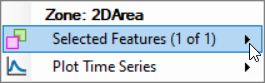
- Choose the Split Polygon | From Drawn Polyline option

- Draw a line that bisects the polygon (cuts across both sides).

- Repeat to create multiple zones
For this example, we created 3 distinct polygons (using the major bridges as split locations)
The final Zones layer is shown below.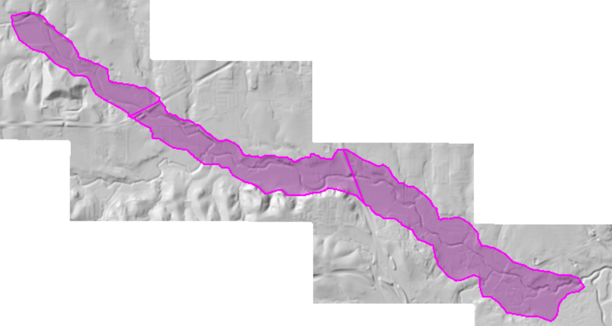
- Open the Zones layer attribute table
- Provide a name for each Zone

- Decide on a Contour Value for each zone using the Plot at Cursor option on the DV map.


- Enter contour Values

Note that larger contour values will result in polygons that encroach more into the floodplain. - Stop Editing the Zones Layer and close the attribute table
Create Encroachment Regions
- Expand the Plans group and the Floodway plan

- Start Editing the Encroachment Regions Layer.
- Generate a preliminary Encroachment Regions polygon by selecting the Generate Floodway Encroachment Polygons | From Map Results menu item from the Encroachment Regions layer.

- The following dialog will appear. Enter information.

- Select the Base plan.
- Select the DV (Max) Map layer
- Provide a Resample Cell Size.
Resampling the map will speed up computations! - Enter Contour information into the Generate Floodway Encroachment Polygons wizard
Note that the larger the Contour Value the smaller the effective floodway.
If you are using Zones (you will need to create zone polygons in the Zones layer), you can override the contour values. - Provide a Filter Tolerance.
- Provide a Simplify Tolerance.
- Press OK to create the polygons
Initial polygons will be created. These are just a starting point for the analysis.
- Edit the polygons, if you wish.
The Encroachment Regions should be modified at (1) all boundary conditions to make sure then go completely to the edge of the 2D Mesh, (2) the floodway boundary to smoothly transition throughout the floodplain, (3) major tributaries that should be included in the floodway encroachment analysis.
- Stop Editing ... and Save Edits
- Close RAS Mapper
Run the Encroached Plan
- Open the Floodway Plan
- Open the Floodway editor from the Options | Unsteady Encroachments menu item

- Select the Base plan
- Enter the Target WSE Rise
- Enter the Fill Slope for the Encroachment Terrain Modification (0.001)
- Enter the Additional Fill for the Encroachment Terrain Modification (0.0)
Adding additional fill may be necessary if the Terrain Modification fill method doesn't correctly fill the floodplain.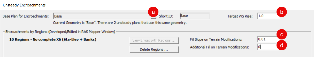
- Press OK to close the editor
- Save the plan
- Compute
- A new RAS Terrain will be added to RAS Mapper. The new RAS Terrain (named "USGSTerrain.Encroached.Encr") will be modified and used for developing Hydraulic Property tables and for floodplain mapping.
- Before the model simulation (a) Terrain Modifications will be used to raise the terrain based on the user-defined encroachment boundaries and Target Rise and (b) then used to update the Hydraulic Property tables for each cell in the 2D Mesh. The terrain will be raised to the target water surface elevation (specified for the Unsteady Encroachment run) along the floodway boundary and slope upwards to the higher elevation away from the boundary. (This process filling the terrain to a higher elevation may fail in highly 2D areas. Adding Additional Fill is often helpful.)
- After the model simulation the modified Terrain model will then be used for floodplain mapping.
Evaluate Encroachment Results
Initial runs will never be the final answer. You will need to evaluate the simulation result, refine your model and re-run.
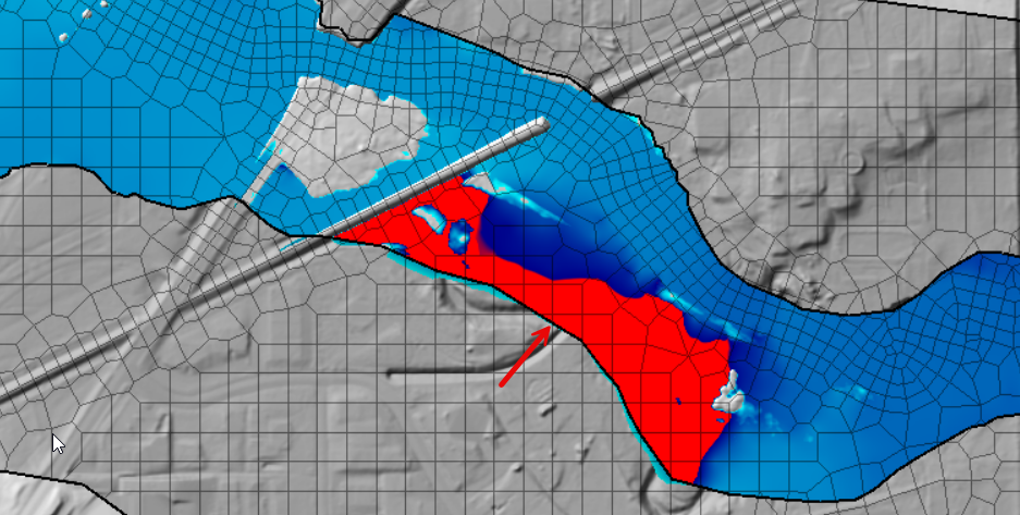
- Turn on the Encroachment Surcharge map. Below in an is a surcharge map for this example.

No. The surcharge is greater than 1ft where map shows red. The initial encroachments will need to be adjusted.
- Use the Profile Plot by right-clicking on the Plan - Encroached | Plot Results Profile option

- You can quickly identify where the encroachment Target Rise is not met in the Profile Plot.
The bottom of the profile plot shows the water surface profile, but the top plot identifies the Target Rise (in Red) compared with the change in water surface from the base run.
- Select one of the Transverse Reference Lines (cross sections) to look at various locations.

The plot above is showing the computed water surface based on the sloping render mode in RAS Mapper. We should look at the average water surface based on flow computed in the solver. - Choose the Options | Variables menu item
- Choose Water Surface (Flow Avg)

- Examine the water surface

The Flow Averaged Water Surface is computed by the computation engine by projecting cell faces onto the Reference Line during the 2D simulation and written out at the Mapping Output Interval for evaluation.
Refine Encroachments
Refining the encroachments to meet the Target Rise and smoothly transition throughout the floodplain is a tedious task. Use whatever time you can to improve the floodplain.
- Use the Terrain surface to make sure the encroachment regions do not encroach into the main river corridor.
- Use the Surcharge map along with the Base WSE inundation to provide information as to where you can encroach.
- Use aerial photography to inform decisions on appropriate encroachment locations.
This is a broad question, but... when you encroach on the river, you are reducing the carrying capacity, but you are also introducing wetted perimeter, which can greatly increase friction losses. Therefore, you can get a localized increase in water surface.
Floodway encroachment analysis is extremely dependent on starting with a good model that has been calibrated to observed data. If the base model does not have appropriate terrain or Mannning's n values, as you try and encroach, the resulting floodway will not respond as expected. This will give both unexpected and erroneous results.
After each refinement, running the new geometry can be an effective way to measure the changes you have implemented. However, depending on the size of the model, this can lead to a very tedious approach if run times are significant. Therefore, this model was developed and refined with the Diffusion Wave approximation of the Shallow Water Equations. Final models should be run using the SWE.
Some preliminary results are shared below.
The results meet the Target Rise criteria. If we were trying to optimize encroachment, however, it appears we could further encroach on the floodplain in many location. We would need to start at the locations where the surcharge was the least and see how sensitive the floodplain was to encroachment! In some places, we have already encroached to the edge of the channel banks.
 plot")
 plot")
