Download PDF
Download page Mesh Generation and Refinement.
Mesh Generation and Refinement
Data Files
You will be working with a section of the White River at Muncie, IN. The data for this tutorial are provided in the zip file.

Objective
In this workshop, you will learn how to create how to generate a 2D Mesh within a 2D Flow Area with HEC-RAS. This workshop will require you to use import a terrain model, develop a 2D mesh, compute hydraulic properties for the grid cells, and view hydraulic table results.
Background
You will be working with a section of the White River at Muncie, IN. You will evaluate how to lay out a 2D Flow Area in the left overbank of the river which is protected by a levee to model a levee breach or over-topping scenario.

Terrain Model Preparation
This part of the workshop will guide you through the process of importing terrain data. The terrain data will be used as the basis for the mesh used for 2D hydraulic computations.
- Start HEC-RAS.
- Save the project using File | New Project and providing a project name.
- Launch RAS Mapper
 .
. - Set the projection for the project using the “prj” file provided in the “GIS_Data” folder.
- Select Project | Set Projection

- Press the folder button and navigate to the “prj” file provided in the “GIS_Data”.

- Select Project | Set Projection
- Import terrain data for use in RAS by selecting the Project | Create New RAS Terrain menu item (or you can right click on the Terrains node on the navigation tree).
- Click the “+” button to add files and navigate to the “Terrain” folder. Select the “tif” file.
- Press the Create button.

Create and Edit New Geometry
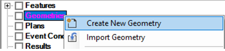
- Create a new Geometry by right-clicking on the Geometries group layer and choosing the Create New Geometry menu item.
- Provide a Name for the Geometry (“Initial Mesh”) and press OK.

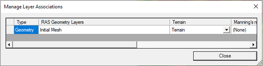
- The dialog to Manage Layer Associations will launch. The terrain you just made is automatically associated with the Geometry Layer you just made (because there are only one of each). This is what you want. So just press Close.
- Right-click on the new Geometry and select Edit Geometry.

- Expand the 2D Flow Areas group
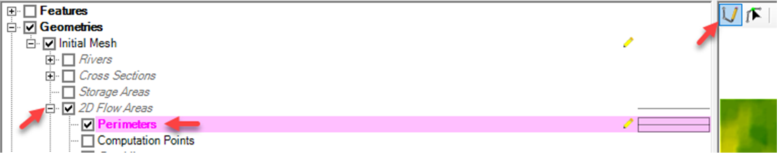
- Create a 2D Flow Area boundary by selecting the Perimeter
- Use to Create New Feature tool
 to digitize the 2D Flow Area boundary.
 (Note, HEC-RAS allows you to import features from shapefile. If you’d like to do so, you can right-click the Perimeter layer and select import Import Features From Shape File. Next, select the Leveed Area.shp file in the GISData folder and press Import….or you can practice using the editing tools.)
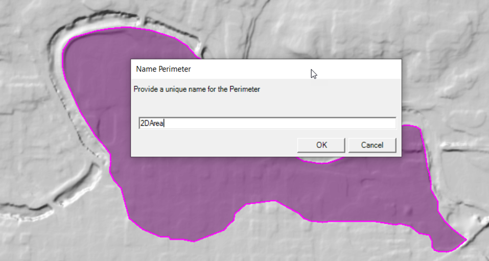
- Double-click to finish (end) the sketch.
- Enter a name for the perimeter in the dialog that appears and press OK.
- Completing the Polygon will Launch the 2D Flow Area Editor.(Note, if you imported your polygon from the shape file you will have to launch this editor by right clicking on the area and selecting Edit 2D Area Properties)

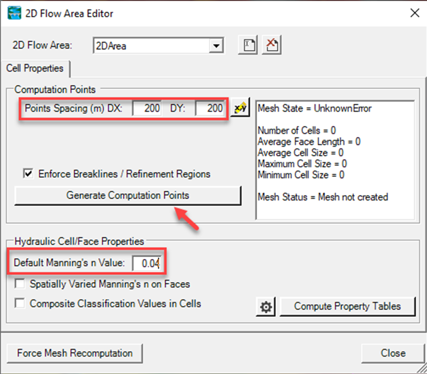
- Enter a point spacing in the 2D Flow Area Editor. Use “200”
- Set the n Value for the region to “0.04”.
- Click the Generate Computation Points button.

- Close the 2D Flow Area Editor.

- Inspect the edge of the 2D Flow Area Mesh for any mistakes in the boundary.
- Turn on the Computation Points Layer to ensure each cell has only one point in it.
- If there are any mistakes, select the Computation Points layer and use the Add New Feature and Edit Feature tools to modify the points.
- When finished, Stop Editing to Save the Geometry!
Compute Hydraulic Properties
- Right-click on the “2D Flow Areas” layer and select Compute 2D Flow Areas Hydraulic Tables. The bottom left of the Mapper window will provide status on the processing.

- Select the “2D Flow Areas” layer by clicking on it (it will turn magenta when selected). (If the Layer is NOT highlighted magenta, the cells and cell faces will not highlight as you select them in the next step.)
- Use the mouse to select Cells and Cell Faces to investigate the cell properties. Right-click on a cell and select Plot Property Table for various 2D cell properties.


Copy and Existing Geometry
- Create a new Geometry by right-clicking on the “Initial Mesh” group layer and choosing the Save Geometry As menu item.
- Provide a Name for the Geometry (“Refined Mesh”) and press OK.
- Start Editing the new Geometry. Right click the new geometry and select Edit Geometry or select the pencil icon.

- Select the Perimeter layer (expand the 2D Flow Areas feature to find it).
- Use the Edit Feature tool to select the 2D Flow Area boundary.
- Right-click to select the Edit 2D Flow Properties menu item.

- Rename the 2D Area “2DArea_2” so you can tell it is the 2nd mesh created.
- Right-click on the polygon and select Rename 2D Area

- Right-click on the polygon and select Rename 2D Area
- Re-generate the mesh in the 2D Flow Area to have 100ft grid cells.
- Open the 2D Flow Area editor.
- Enter 100 for the Point Spacing.
- Press the Generate Computation Points button. A warning comes up that you will be deleting the existing points and generating new ones.

- Close the 2D Flow Area Editor.
- Inspect the mesh and fix errors.
- Cell Faces control the movement of flow from cell to cell.
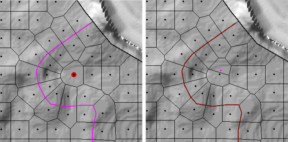
Add breaklines to improve the mesh by enforcing cell faces along high ground.- Select the Breaklines Layer.

- Use the Add New Feature to create a new breakline
- Zoom into the portion of high ground along the terrain south of the bridge near the middle of the mesh.

- Draw a breakline along this high ground. Double-click to complete the line.

- Provide a name for the breakline in the dialog that appears or accept the default name.
Note what happens the mesh with the breakline. - Right-click on the new breakline and select the Enforce Breakline option (or right-click on the Break Lines Layer and choose Enforce All break lines).

- Fix any errors by adding a new point or removing an existing point.
(To add a new point, select Computational Points) under the 2D Flow Areas and select the Add New Feature tool.
- Select the Breaklines Layer.
Refine the Breakline
- Right-click on the breakline and choose Edit Breakline Properties.
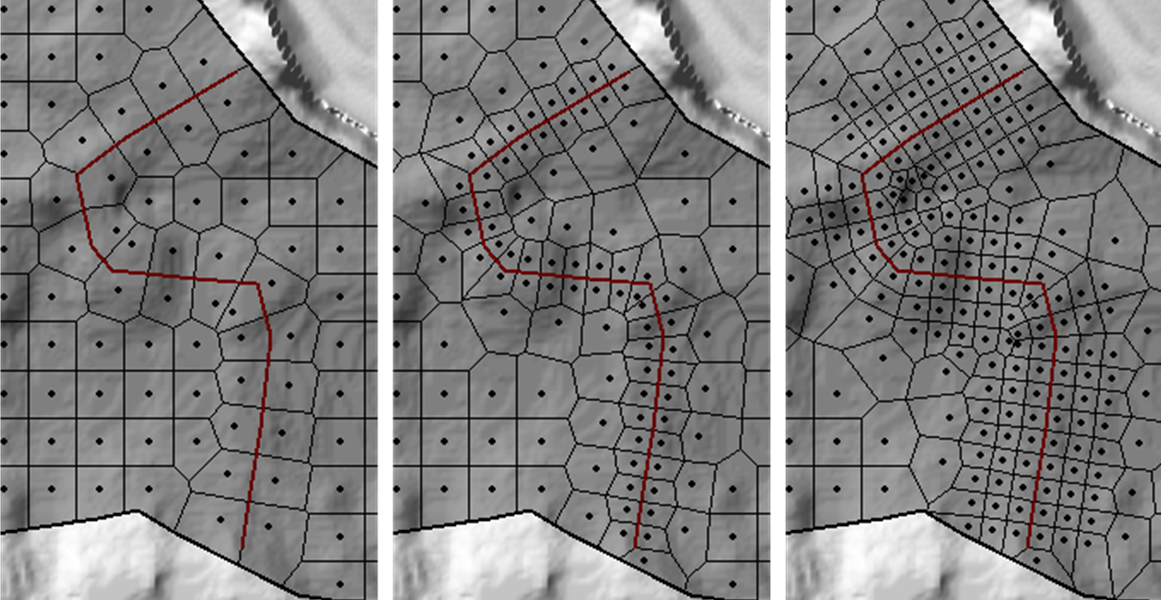
- Try different breakline parameters to see how the breakline works.
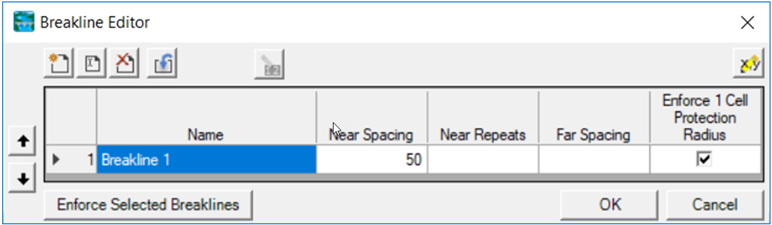
Repeated changes to the breakline using the Enforce Selected Breaklines button will ONLY make changes based on the current computation points.
To PROPERLY apply a breakline you will need to open the 2D Flow Area Editor and Generate Computation Points with the Enforce Breaklines / Refinement Regions option checked. This will regenerate points at the prescribed spacing and then enforce the breakline its parameters.
- What looks to be a good starting point for breakline spacing?
Refine a Mesh using Refinement Regions
In the next step, you are going to create a mesh and refine it to better represent the ground surface using refinement regions.
- Create a copy of the geometry “Initial Mesh” geometry by right-clicking on the Geometry and choosing Save Geometry As (name it “Mesh 3”).
- Start Editing the new Geometry.
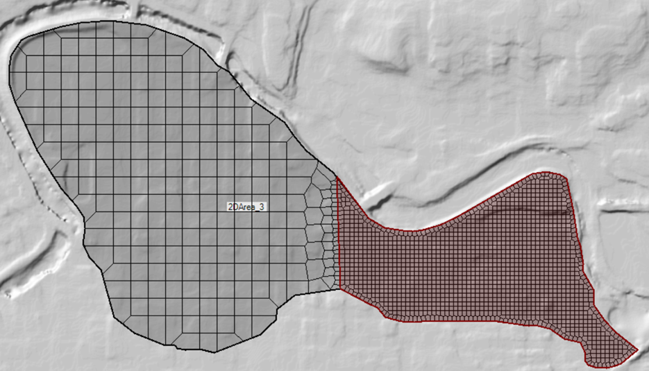
- Rename the 2D Area to “2DArea_3” so you can tell it is the 3rd mesh created.
- Cell Faces control the movement of flow from cell to cell. Add refinement regions to improve the mesh by enforcing cell faces along high ground and densifying the computation points
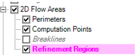
- Select the Refinement Regions layer
Use the Add New Feature to create a new region for the upper portion of the 2D Area where the land surface is highly variable.
Trace the eastern portion of the Perimeter with the refinement region.

Provide a name for the region.
Open the Refinement Region Editor and provide a cell spacing. Right-click on the Refinement Region and select the Edit Refinement Region Properties menu item.

Enforce the new refinement region.
Right-click on the refinement region and select Enforce Region.
Create additional refinement regions, adjust parameters, and recompute the mesh to see how the changes are applied.
- Select the Refinement Regions layer