Save the project using File | New Project and providing a project name.
Launch RAS Mapper .
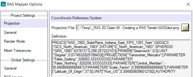
Select Project | Set Projection for Project and navigate to the "projection.prj" provided in the "GISData" folder. This sets the coordinate system for all the data you will view in RAS.
Press OK to accept the file.
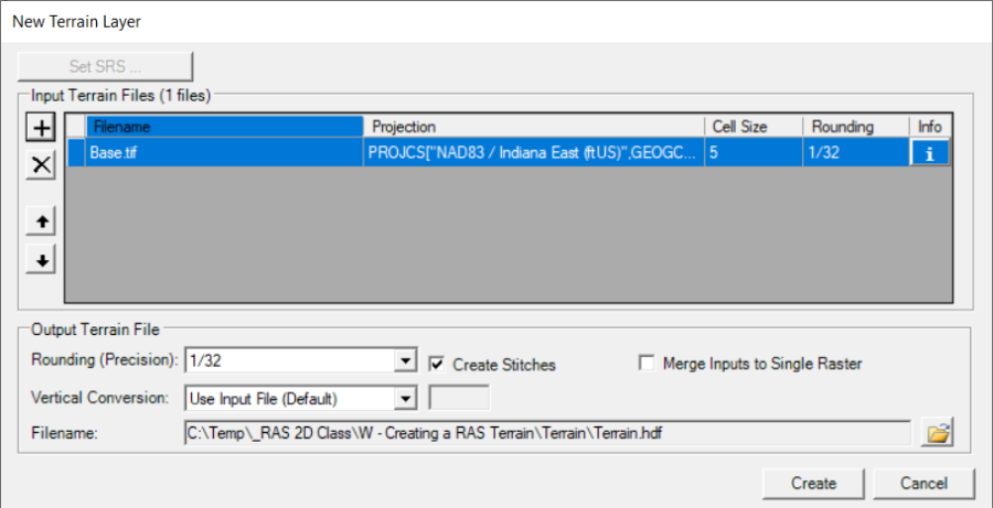
Select the Project | Create New RAS Terrain menu item (or right-click Terrains and choose the Create aNew RAS Terrain menu item) to import the terrain model.
Click the "+" button to add files and navigate to the "Terrain" folder. Select the "base.tif" file.
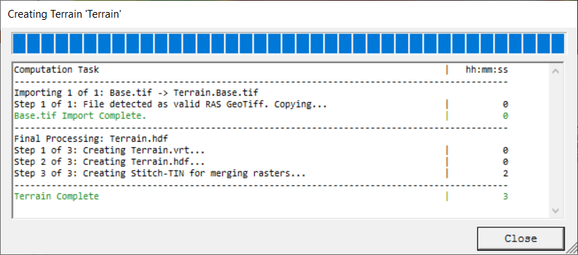
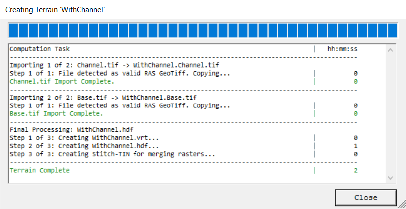
Press the Create button.As the Terrain is created, a computation window will inform you of progress.
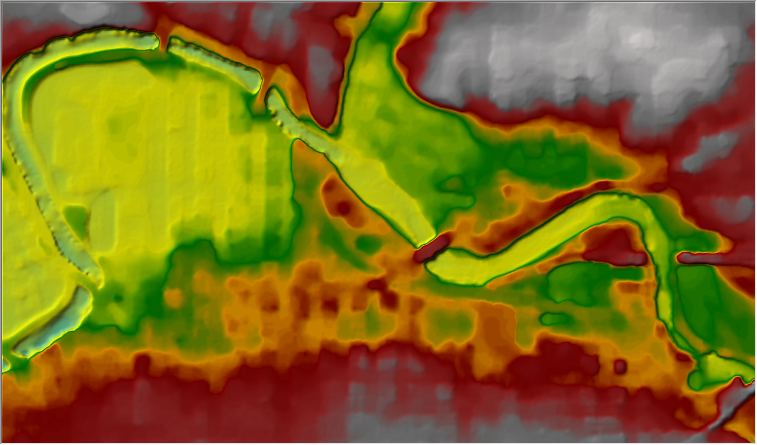
Double-click on the Terrain Layer to access its Properties.
Click on the Plot Hillshade option.Play with the Z Factor to find a value you prefer.
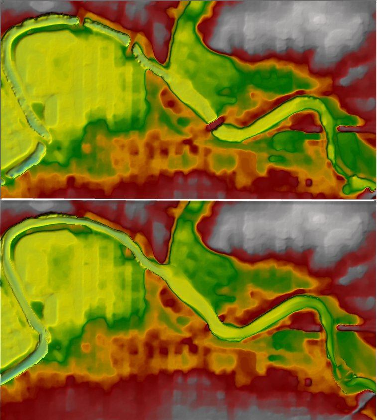
Click on the Plot Contours option. Play with the Interval. Experiment with the option until the terrain looks good to you. Note the presence of high ground in the middle of the channel at bridge locations.
Creating a RAS Terrain from Multiple Datasets
This task will take you through the process of creating a RAS Terrain from 2 different terrain models: channel data and overbank terrain, in order to capture the channel geometry where there is currently high ground at the bridge locations.
Create Grid of Channel Data
Open RAS Mapper
Select the Project | Create New RAS Terrain menu item
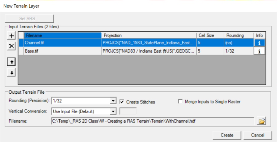
You will have to add to 2 different files. Make sure that the "priority" is set properly. The top layer should be the channel geometry, followed by the overbank. If you add them in the wrong order, you can reprioritize them by highlighting on of them, and clicking the up or down arrows on the left-hand side of the menu.
Add the "Channel.tif"
Add the "Base.tif"
Change the output filename to "WithChannel" by clicking the open folder icon in the bottom right corner of the menu. Enter the new name, and click save.
Press the Create button.
Change the Layer Properties for the "WithChannel" Terrain.
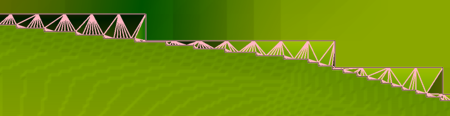
Turn on the Plot stitch TIN edges for the "WithChannel" Terrain.
Investigate the stitching – a TIN which is the interpolation between the in-channel data and the overbank data. Compare with the base Terrain model.
Compare the two terrain models (with and without bridge elevations).