Download PDF
Download page Creating Hydraulic Property Tables for 2D Flow Areas.
Creating Hydraulic Property Tables for 2D Flow Areas
As previously mentioned, the 2D Computation Mesh is preprocessed into an elevation – volume curve for each cell, and a series of hydraulic property curves for each cell face (elevation vs. wetted perimeter, area, and roughness). This pre-processing is accomplished in RAS Mapper. The hydraulic property tables are derived from the details of the underlying terrain used for the model, as well as any user defined Manning's n by land cover relationships set in the geometry file. A terrain model is required to use 2D modeling within HEC-RAS. The terrain data is also required in order to do any mapping of the computed results, for both the 1D and the 2D areas of the model. Please review Chapter 2 of this manual for instructions on creating a Terrain model for use in 2D modeling and results visualization.
Once a terrain model is created, and optionally a Manning's n by Land Cover table, then the following steps are required to create the hydraulic property tables for the 2D cells and cell faces, which are used in the 2D hydraulic computations:
Associating a Terrain and Manning's Layer with a Geometry
After a new terrain layer and Manning's n layer are added, the user must associate the terrain and Manning's layers with any or all of the geometry files within the HEC-RAS project. This is accomplished in RAS Mapper by right clicking on the Geometries layer at the top of the layer list (on the left hand side of the RAS Mapper window), then selecting the Manage Geometry Associations option from the popup menu. When this is done a window will appear, as shown in Figure 3-17, in which the user can select a terrain layer for each geometry file.

After associating all of the geometry files with the terrain and Manning's n layer(s), select the Close button. This will ensure that these associations are saved.
2D Geometric Preprocessor
Overview of Cell and Face Properties
Each cell, and cell face, of the computational mesh is preprocessed in order to develop detailed hydraulic property tables based on the underlying terrain used in the modeling process (Casulli, 2008). The 2D mesh pre-processor computes a detailed elevation-volume relationship for each cell. Each cell face of a computational cell is pre-processed into detailed hydraulic property tables (elevation versus wetted perimeter, area, roughness, etc…). This allows the user to use larger computational cells, while keeping the details of the underlying terrain. The net effect is that larger cells results in fewer computations, which means much faster run times. Additionally, HEC-RAS will produce more detailed results for a given cell size than other models that use a single bed elevation for each cell and cell face.
An example of how HEC-RAS pre-processes cells and faces into detailed property tables is shown in Figures 3-18 through 3-21. Shown in Figure 3-18 are the details of the underlying terrain within a single computational cell.

When the 2D Geometric Pre-processor runs a detailed elevation-volume relationship is developed for each cell. See an example of this in Figure 3-19 below. 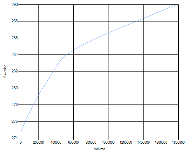
In addition to the processing of the cells, the faces of the cells are preprocessed into tables of elevation versus area, wetted perimeter, and roughness. See Figure 3-20 below:

As shown in Figure 3-20, each cell face is like a detailed cross section. So the flow of water into, through, and out of a cell is controlled by the details of these face properties, and the cell elevation-volume relationship. The benefit of this is much greater hydraulic details at the cell level over other models that use a single elevation for each cell and face. With HEC-RAS, users can have much larger cells, but still retain great hydraulic detail within a cell. Additionally, HEC-RAS cells can be partially wet (i.e., water does not have to cover the entire cell, and can move through a portion of the cell). An example of this is shown in Figure 3-21.

Shown in Figure 3-21 is an example of how the computational cells in HEC-RAS contain enough hydraulic detail such that flow can move through a channel, even though the channel is smaller than the cell size. In the above example, the 2D cells are 500 x 500 ft (the underlying terrain is 2 x 2 ft grids). Water will move through the channel portion of the cells, because the details of the channel cross sections are contained within the cell faces. Additionally, the details of the elevation-volume relationship in the channel are contained within the cell hydraulic properties table. In this type of example, flow can move through a channel in a 1D-type of mode, while flow in the overbank areas will be 2D from cell to cell. If the user wants more detail within the channel, such as two-dimensional flow velocities and varying water surface elevations, then a cell size in that would allow 5 to 7 (or more) cells across the channel is needed. The smaller cell size will allow the model to capture the two dimensional flow effects within the channel itself. However, if the user only needs to capture the two-dimensional flow effects on the floodplain, then the approach shown in Figure 3-21 is a viable option. This type of model is not a detailed channel model, but it does allow water to move through the channels in a 1D fashion, with a reasonable amount of conveyance computed for the channel, based on the terrain at the cell faces.
The 2D flow capabilities in HEC-RAS can be used in many ways. The user can develop a mesh with very small cell sizes that can be used to model both channels and floodplains in great detail. Or the user can use larger cell sizes, which will give you less detail in the channel, but still 2D flow hydraulics in the floodplain. The level of detail the user chooses depends on what is being modeled, and the purpose of the study. HEC-RAS provides the user with the maximum amount of flexibility in modeling the details of a channel and the floodplain in 2D. Preprocessing the cells and cell faces into detailed hydraulic property tables is an advantage over 2D models that use a single elevation for each cell (flat cells), and a single line for each face (flat or linear sloping faces).
Running the 2D Geometric Preprocessor
After associating the geometry files with the terrain layer, the user can run the 2D flow area geometric pre-processor from within RAS Mapper. This step does not have to be done in RAS Mapper. If the user does not run the 2D Geometric preprocessor in RAS Mapper, it will automatically be done as a separate process during the unsteady flow computations.
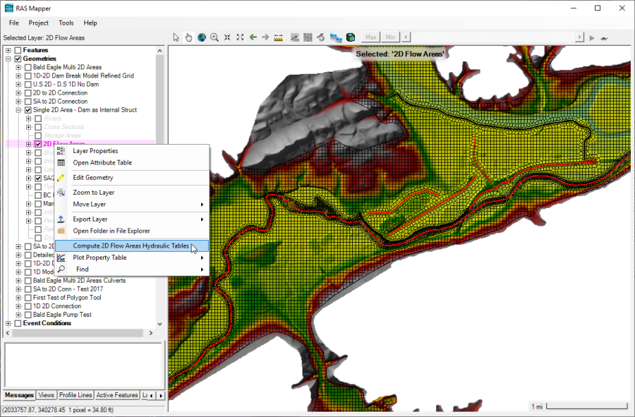
In the Geometry group there will be a sub layer called 2D flow area. Checking the box for this layer will turn on the mesh for all of the 2D flow areas contained within that geometry file. In this example, there is only one 2D flow area. Right click on the sub layer called 2D flow area, then select the option labeled Compute 2D Flow Areas Hydraulic Tables (see Figure 3-22). This is the option to pre-process the 2D flow area computational cells and faces into detailed tables based on the underlying terrain data. If the user does not do this step here, the HEC-RAS user interface will detect that the pre-processing step has not been done, and it will do it during the unsteady flow computational process (right before it performs the existing 1D pre-processing of the cross sections and hydraulic structures). Also, if the user later changes anything about the 2D area (adds, moves, deletes cells, changes Manning's n-values, etc…), then the 2D pre-processor step will automatically be rerun during the unsteady flow computational process.