Download PDF
Download page Internal Boundary Conditions.
Internal Boundary Conditions
Internal Flow Hydrograph
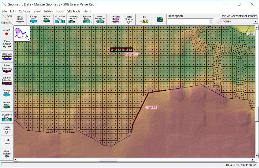
The user has the option to add a flow hydrograph as an internal boundary condition. To add an internal boundary condition line, from the Geometric Data editor, select the SA/2D Area BC Lines ![]() tool, then draw an internal line inside of the 2D Flow Area (shown below). The internal boundary condition (BC) line can encompass one or more 2D cells. Once the line is drawn, a name for the BC line must be entered. An example of a created internal BC line named “Internal BC,” as well as an example of an external BC line (labeled “edge BC”) is shown in the figure below.
tool, then draw an internal line inside of the 2D Flow Area (shown below). The internal boundary condition (BC) line can encompass one or more 2D cells. Once the line is drawn, a name for the BC line must be entered. An example of a created internal BC line named “Internal BC,” as well as an example of an external BC line (labeled “edge BC”) is shown in the figure below.

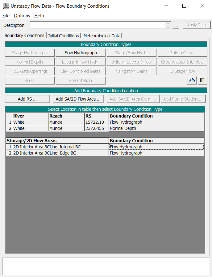
After an internal BC line is drawn in the Geometric Data editor, the user can open the Unsteady Flow Data editor (opened from the HEC-RAS main window by clicking the ![]() button) to attach flow hydrographs to the internal BC lines. Once the Unsteady Flow Data editor is open (shown in the figure below), select the Boundary Conditions tab, and view in the “Storage/2D Flow Areas” table that there is a row for the newly created internal boundary condition line(s) (e.g., 2D Interior Area BCLine: Internal BC in Figure 4‑4) that were created in the Geometric Data editor.
button) to attach flow hydrographs to the internal BC lines. Once the Unsteady Flow Data editor is open (shown in the figure below), select the Boundary Conditions tab, and view in the “Storage/2D Flow Areas” table that there is a row for the newly created internal boundary condition line(s) (e.g., 2D Interior Area BCLine: Internal BC in Figure 4‑4) that were created in the Geometric Data editor.

As shown in the figure above, the created internal BC lines will be listed in the boundary conditions table, and will allow the user to attach a flow hydrograph to a selected BC line. If the BC line crosses more than one cell, flow is distributed across the cells based on the percentage of the line length that crosses that cell. For example, if a cell contains 20% of the BC line length, then the cell will receive 20% of the flow each time step.
Use with HEC-HMS Results
When using results supplied by HEC-HMS within a 2D Flow Area as internal boundary conditions, special care needs to be taken to avoid double routing. Specifically, when using unit hydrograph transform methods (e.g., ModClark) within HEC-HMS to compute subbasin outflow hydrographs, the computed results represent discharges AT THE OUTLET and SHOULD NOT be distributed over a significant longitudinal length (e.g., greater than 1 mile) or area.
In general, HEC-RAS boundary condition lines should be drawn perpendicular to expected flow paths at the location of interest. If an internal boundary condition line is drawn along the watercourse a significant distance upstream of the outlet of the subbasin, the peak flow and resulting elevation from HEC-RAS will be underestimated due to double routing of the hydrograph from HEC-HMS. If there are additional locations upstream of the subbasin outlet where flow estimates and stages are important, additional subbasin delineations will be required rather than applying the hydrograph over a long longitudinal distance.
Precipitation
This Precipitation option can be used to apply rainfall excess (rainfall minus losses due to interception and/or infiltration) directly to a 2D flow area. To apply a precipitation boundary condition to a 2D flow area (or storage area), open the Unsteady Flow Data editor and select the button that is labeled Add Storage Area from the Add Boundary Condition Location table. Select the 2D flow area of interest to add to the table. Once the 2D flow area is in the Select Location in table then select Boundary Condition Type lower table, select the blank field under the Boundary Condition column (shown in the figure above), then select the Precipitation boundary condition type. The Precipitation boundary condition type selection opens an editor that will allow users to either read the precipitation data from HEC-DSS or enter the data as a time series into a table directly. Precipitation is applied equally to all cells within the 2D flow area.