Download PDF
Download page Creating Land Cover, Manning’s n values, and % Impervious Layers.
Creating Land Cover, Manning’s n values, and % Impervious Layers
A spatially varying land cover layer can be created in RAS Mapper, and then associated with a specific geometry data set. Once a land cover data set is created, the user can specify Manning’s n values to be used for each land cover type. Additionally, the user can create their own land cover classification polygons (user defined polygons), in which they can override the base land cover layers within that polygon and define a new land cover type. User defined classification polygons are often used for channel areas as national land cover data sets often do not adequately define the correct area for the main channels. The creation of user defined landcover classifications will allow users to create a good set of base Manning’s n values for these user defined classification polygons. More than one polygon can be drawn and given the same name. However, only one Manning’s n value can be set for each user defined land cover classification polygon. So, if the Manning’s n values need to be different, then the polygons must have different names. Users can also specify percent impervious for each of the land cover types. Percent impervious is optional and only necessary if the user is modeling precipitation and infiltration.
Once a Land Cover layer (with Manning’s n values set) is created and associated with a specific Geometry data set, the user can create Calibration Region polygons. A Calibration Region polygon is used to override all the Manning’s n values associated with land cover within the polygon. Created Calibration Regions only apply to that specific Geometry, and do not change the base land cover/Manning’s n value layer. In other words, Calibration Regions allow users to come up with different Manning’s n values for different calibration events, if necessary.
This section of the manual provides instructions for creating a Land Cover data set, Manning’s n Values and Percent Impervious, User defined land cover classification polygons, associating Land Cover/Manning’s n with Geometry Data, and Manning’s n Calibration Regions.
Creating a Land Cover Data Set
In the current version of HEC-RAS, users can import land use information in both polygon (shapefile) and gridded formats. Custom user defined Shapefile layers can be created in HEC-RAS Mapper. Gridded landcover data can be obtained from U.S. Geological Survey (USGS) websites (National Land Cover Database, NLCD 2016 and USGS Land Use Land Cover modeling, LULC), as well as other sources. RAS Mapper allows the user to add multiple land use data input files and file types to create a single land use coverage layer in HEC-RAS. For example, a user may want to use the USGS NLCD 2016 gridded land use data as the base land use coverage data. However, a user may want to also find or generate a polygon coverage (shapefile) that is more accurate for many of the areas within their study region (i.e., the main channel regions, buildings, roads, etc…). By setting the more accurate shapefile as the higher priority, the land use from the shapefile will be used unless it does not cover portions of the area, then the USGS gridded data will be used for those areas. RAS Mapper ingests the various land use data types and creates a combined land cover layer and stores it as a GeoTIFF file (there is also a companion *.hdf file generated).
To create a spatially varying land cover layer within HEC-RAS, go to RAS Mapper, then right click on Map Layers in the tree on the left, then select Create New RAS Layer| Land Cover Layer. This selection will bring up the window shown in Figure 3-16. The Land Cover Layer window is broken into three sections: Input Files, Unique Classification Names for Selected File, and Output File. The Input Files section is for selecting the grid and shapefiles to be used as input, as well as setting their priority. The Unique Classification Names for Selected File section is used to display the numeric value (Integer) and the text label of the land cover data for the file currently selected (highlighted) in the Input Files section. The Output File section is used to show what HEC-RAS will use for the RAS Classification name and numeric ID.
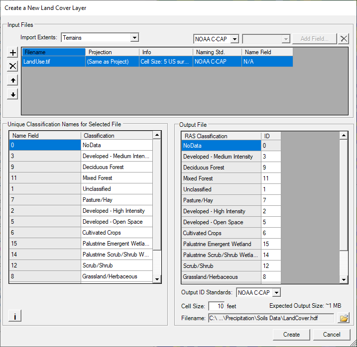
The Create a New Land Cover Layer editor (Figure 2-10) allows the user to select one or more land use files of varying type. This is accomplished under the Input Files section by selecting the Plus (+) button. Once the plus button is selected a file chooser will come up allowing the user to select a land use coverage file. If more than one land use file is selected, use the Up and Down arrows to select and move a file in the Input Files section to set the priority of the listed files. The file at the top of the list has the highest priority, and so on. Because HEC-RAS supports multiple land use files and types, the user will have to either select one of the established naming conventions or enter their own naming convention for each land use type.
To set the naming convention for a shapefile, from the Input File section of the editor, select (highlight) a shapefile, the Name Field column actives. From the dropdown list located above the input files table, select a shapefile field (column contained in the shapefile) to be used for name field. To set the naming convention for a gridded land cover data set, from the Input File section of the editor, select (highlight) a gridded land cover data set, and only the Naming Std. field activates and is available for defining the names of land use types. Currently there are three options for defining the names of the land use types: NLCD 2016 (which is from the USGS 2011 land use data coverage); Anderson II (developed by James R. Anderson, et al., from the USGS in 1976); and NOAA C-CAP. For the example provided in Figure 2-10, the NOAA C-CAP land use type names option is selected from the Naming Std. dropdown menu (located above the input files table) in the Input Files section.
When you select a land cover layer in the Input File section of the editor, the “Unique Classification Names for Selected File” section of the editor will show what is contained within the file for the Name Field (integer value or text label), and also what HEC-RAS will use as an identifier for that specific land cover type. Because different land cover data sources use different naming conventions, if the user has more than one input file, the software must come up with a single naming convention to use for all of the data. The combined naming convention that HEC-RAS will use is shown in the Output File section of the window. The Output File section shows the final naming convention it will use, along with the integer ID’s. Manning’s n values could have been selected from a Shapefile, or the user can edit/enter them directly into the Land cover data table.
From the Create a New Land Cover Layer editor (Figure 2-10), from the Output File section, the user can choose an Output ID Standard from the dropdown located below the output file table. The output ID standard is generally used when a shapefile has been selected and the user does not wish to apply one of the USGS naming standards to that file. If more than one input land cover file has been added to the Input Files table, then the Naming Std. column will automatically contain the Custom option, as a single standard will generally not work for multiple land cover types. Also, when using more than one land cover layer type (shapefile and grid), there will be different naming conventions within the two files for the same land cover type. USGS naming conventions use specific integer ID’s for associated land cover types; however, the integer ID’s get assigned to land cover types for shapefiles. If the same ID gets assigned to two different land cover types, the software will display a “Duplicate IDs” error message in red below the output table. The user must change one or more of the duplicate ID’s to a unique integer identifier, currently not used in the table before creating the land cover layer.
From the Create a New Land Cover Layer editor (Figure 2-10), from the Output File section, the filename and output directory for the new land classification layer is shown at the bottom of the section. The user should select a directory to be used for the HEC-RAS land cover layer, and also enter a name for this new layer. RAS Mapper takes all of the input layers and creates a single land cover output layer in the *.tif file format. The last step before creating a Land Classification dataset is to enter an appropriate cell size (i.e., 1, 2, 5, 10 ft) that takes into account the computational cell size being used and the spatial accuracy needed for the land classification (and therefore roughness) values. After all the data is entered press the Create button, RAS Mapper will read the input file layers and convert them into a single GeoTIFF file in the user define output directory. A progress window will open displaying the file creation progress and inform the user when the file has been created. From the progress window, click the OK button to close the progress window and the Create a New Land Cover Layer editor (Figure 2-10).
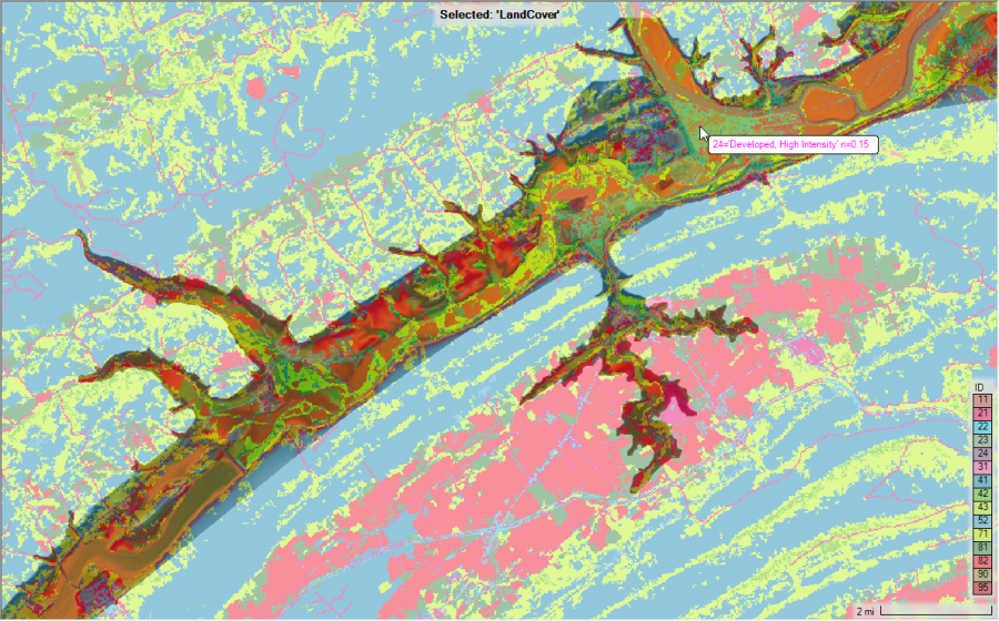
Figure 2-11 provides an example of a Land Cover layer with Land Classifications created and displayed in RAS Mapper. The user can control the color of each land use category, and the transparency used to display the polygons. The display of the land use classification is controlled by right clicking on the Land Cover layer and selecting Image display properties from the shortcut menu. This command opens a window allowing the user to control the colors and transparency of the polygons.
Manning's n Values and Percent Impervious
Once a Land Cover layer has been created, the user can then build a table of Land Cover versus Manning’s n values, which can then be used in defining roughness values for 2D flow areas and 1D river reaches. The created Land Cover versus roughness table is developed from within the HEC-RAS Mapper software, directly within the Land Cover layer. To create the Manning’s n vs. Land Cover table, from the RAS Mapper main window (Figure 2-1), from the Layers window (Figure 2-1), under Map Layers, right click on the Land Cover layer of choice, and from the shortcut menu, click Edit Land Cover Data. The Edit Land Cover Data command opens the Data Table Editor (Figure 2-12).
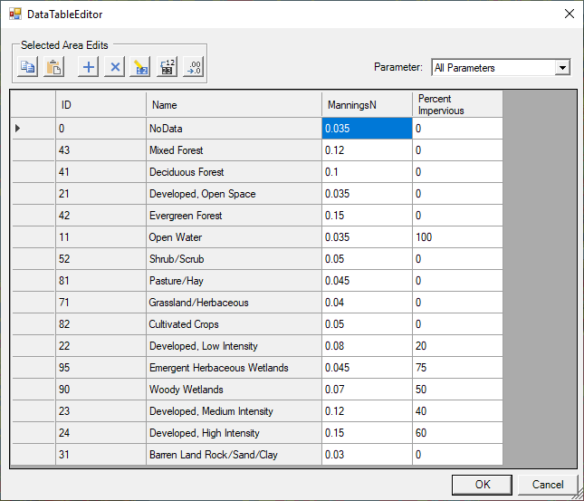
As shown in Figure 2-12, the user must define Manning's n values for all of the land classification types, including the NoData field. The user entered Manning's n values will be considered to be the base Manning's n values for this land cover layer. Additionally the user can define Percent Impervious for each Land Cover Classification type. Percent Impervious is only needed in the user intends to use precipitation and infiltration features within HEC-RAS.
User Defined Land Cover Classification Polygons
In addition to establishing Manning’s n values for each of the land cover classifications within the land cover layer, users have to option to override these values by creating user defined Classification Polygons. For example, the national based land cover data sets are not well defined for the main channel areas of a river system. Users will need to create their own main channel polygons to ensure they can establish a good set of base Manning’s n values for the entire channel. Typically, a river system will be broken up into many user defined polygons, one polygon for each Manning’s n value region.
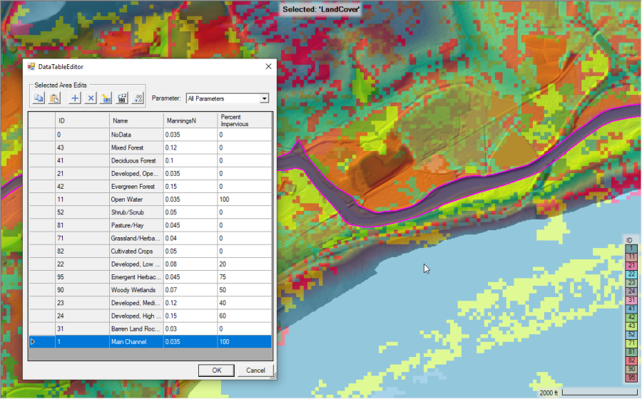
To create user defined land cover classification polygons, right click on the Classification Polygons layer underneath the desired Land Cover layer, then select Edit Layer. This puts RAS Mapper into edit mode and will allow you to create new or edit existing classification polygons. An example showing a single user defined land cover Classification Polygon, for the “Main Channel,” is provided in Figure 2-13. The example provided in Figure 2-13, displays the Main Channel with a user defined classification for the Manning’s n value of 0.035 and a percent impervious of 100. Generally, several user defined land cover classifications will be developed for a land cover data layer to reclassify main channel areas, roads, parking lots, buildings, or anything else that is not well defined in the base land cover data layer.
Associating Land Cover/Manning's n with Geometry Data
Once the user has created a Land Cover layer and added some of their own user defined classification regions, they must associate land cover layers with geometry file(s). To associate a Land Cover layer with a geometry file, right click on the Geometries layer (on the left side of the RAS Mapper window) and select Manage Geometry Associations from the shortcut menu. The Manage Geometry Associations window (Figure 2-14) opens, this window allows the user to select the desired layers to associate with each of the Geometry files in the project.

As shown in Figure 2-14, the Geometry Associations table allows the user to associate the following information:
- Terrain: This must be a Terrain data set created from within HEC-RAS Mapper. This layer association is required.
- Manning's n: Land Cover layer containing Manning's n values to use as base Manning's n values for the associated Geometry. This layer is required in order to have spatially varying Manning's n values within 2D Flow Areas.
- Infiltration:Infiltration Layer containing land cover, soils, and infiltration parameters for one of the available infiltration methods. This layer is Optional depending upon modeling approaches.
- % Impervious: Land Cover layer containing % Impervious values to use with associated Geometry. This layer is Optional depending upon modeling approaches.
- Soils: Soils Layer to be associated with Geometry. This Layer is Option, and only required for 2D Sediment Transport modeling.
Manning's n Calibration Regions
Once a Land Cover/Manning’s n layer has been developed and associated with a specific Geometry data set, the user has the option to create Manning’s n Calibration Regions that will only be applied to that specific Geometry data set. To calibrate a hydraulic model, it may be necessary to increase or decrease Manning’s n values on a reach-by-reach basis for a specific geometry or event. This process can be accomplished by developing Manning’s n calibration regions and using those regions to raise or lower all the Manning’s n values contained within that region or polygon.
Manning’s n Calibration regions/polygons are created within the Manning’s n layer of a specific Geometry data set. To create Manning’s n calibration regions, open HEC-RAS Mapper and from the Layers window expand the Geometry layer to be edited (e.g., Expanded Model – Final Mesh in Figure 2-15). Then expand the Manning’s n layer for that Geometry data set. To create or edit Manning’s n Calibration Regions, right click on the Calibration Regions sublayer and select Edit Geometry from the shortcut menu. This option allows the user to create new regions or edit existing regions. Once a region is created user can redefine all the Manning’s n values within that region for each land cover type. An example of a model with Calibration Regions for the main channel areas is shown in Figure 2-15.
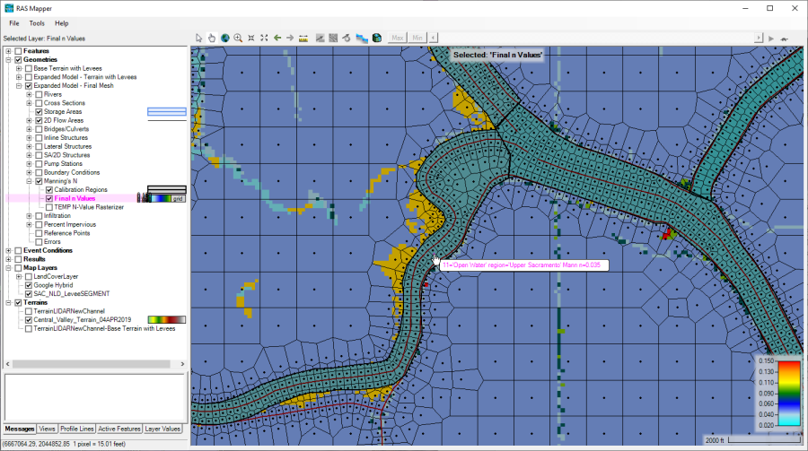
Once the user has drawn the Manning's n Calibration regions for a geometry, the Manning's n values can be edited in a table by right clicking on the Calibration Regions layer and selecting Edit Manning's n Values. When this is done, a table will appear that allows the user to edit the Manning's n values for all the calibration regions (Figure 2-16).
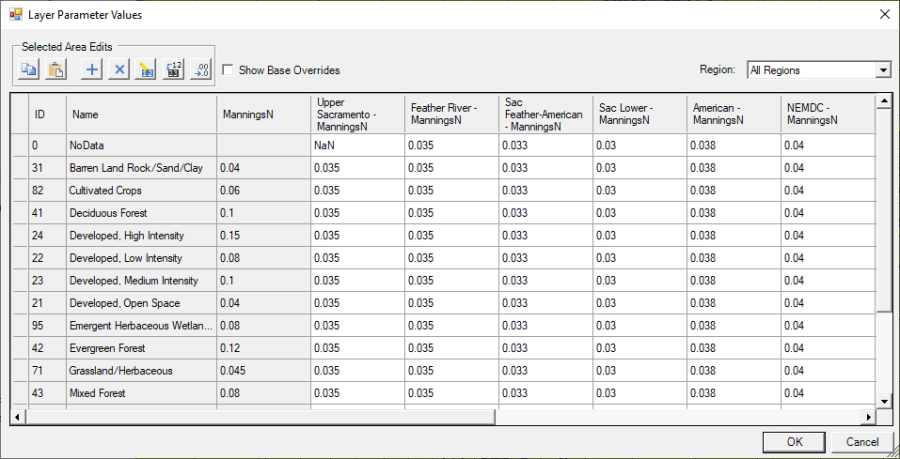
This Manning’s n by Land Cover and the Calibration Regions will be used during the 2D flow area pre-processing stage (i.e., the process where the software creates the cell and cell face property tables). To get these Manning’s n values into the 2D flow area property tables, the 2D flow area hydraulic property tables must be recomputed. When the cell faces are processed, the Manning’s n value selected will be based on finding the cell face center, then the corresponding Manning’s n value from the land cover layer. If there is no Land Cover layer defined for a specific cell face, then the default Manning’s n value entered into the 2D flow area editor will be used for that cell face. For HEC-RAS Version 6.0, the software will select only one Manning’s n value for the entire cell face. Future versions of HEC-RAS will allow for multiple Manning’s n values across each cell face.
Examples of typical Manning’s n value ranges for the various NLCD Land Cover types is shown in Table 2-1. These n values are for appreciable depths of flow, and are not meant for shallow overland flow. Shallow, overland flow Manning’s n values are generally much higher due to the relative roughness compared to the flow depth.
Table 2-1. Example Manning's n values for various NLCD Land Cover Types.
NLCD Value | n Value Range | Description |
|---|---|---|
11 | 0.025 - 0.05 | Open Water- areas of open water, generally with less than 25% cover of vegetation or soil. This is for natural streams on mild to moderate slopes. |
12 | n/a | Perennial Ice/Snow- areas characterized by a perennial cover of ice and/or snow, generally greater than 25% of total cover. |
21 | 0.03 - 0.05 | Developed, Open Space- areas with a mixture of some constructed materials, but mostly vegetation in the form of lawn grasses. Impervious surfaces account for less than 20% of total cover. These areas most commonly include large-lot single-family housing units, parks, golf courses, and vegetation planted in developed settings for recreation, erosion control, or aesthetic purposes. |
22 | 0.06 - 0.12 | Developed, Low Intensity- areas with a mixture of constructed materials and vegetation. Impervious surfaces account for 20% to 49% percent of total cover. These areas most commonly include single-family housing units. |
23 | 0.08 - 0.16 | Developed, Medium Intensity -areas with a mixture of constructed materials and vegetation. Impervious surfaces account for 50% to 79% of the total cover. These areas most commonly include single-family housing units. |
24 | 0.12 - 0.20 | Developed High Intensity-highly developed areas where people reside or work in high numbers. Examples include apartment complexes, row houses and commercial/industrial. Impervious surfaces account for 80% to 100% of the total cover. |
31 | 0.023 - 0.030 | Barren Land (Rock/Sand/Clay) - areas of bedrock, desert pavement, scarps, talus, slides, volcanic material, glacial debris, sand dunes, strip mines, gravel pits and other accumulations of earthen material. Generally, vegetation accounts for less than 15% of total cover. |
41 | 0.10 - 0.20 | Deciduous Forest- areas dominated by trees generally greater than 5 meters tall, and greater than 20% of total vegetation cover. More than 75% of the tree species shed foliage simultaneously in response to seasonal change. |
42 | 0.08 - 0.16 | Evergreen Forest- areas dominated by trees generally greater than 5 meters tall, and greater than 20% of total vegetation cover. More than 75% of the tree species maintain their leaves all year. Canopy is never without green foliage. |
43 | 0.08 - 0.20 | Mixed Forest- areas dominated by trees generally greater than 5 meters tall, and greater than 20% of total vegetation cover. Neither deciduous nor evergreen species are greater than 75% of total tree cover. |
51 | 0.025 - 0.05 | Dwarf Scrub- Alaska only areas dominated by shrubs less than 20 centimeters tall with shrub canopy typically greater than 20% of total vegetation. This type is often co-associated with grasses, sedges, herbs, and non-vascular vegetation. |
52 | 0.07 - 0.16 | Shrub/Scrub- areas dominated by shrubs; less than 5 meters tall with shrub canopy typically greater than 20% of total vegetation. This class includes true shrubs, young trees in an early successional stage or trees stunted from environmental conditions. |
71 | 0.025 - 0.05 | Grassland/Herbaceous- areas dominated by gramanoid or herbaceous vegetation, generally greater than 80% of total vegetation. These areas are not subject to intensive management such as tilling, but can be utilized for grazing. |
72 | 0.025 - 0.05 | Sedge/Herbaceous- Alaska only areas dominated by sedges and forbs, generally greater than 80% of total vegetation. This type can occur with significant other grasses or other grass like plants, and includes sedge tundra, and sedge tussock tundra. |
73 | n/a | Lichens- Alaska only areas dominated by fruticose or foliose lichens generally greater than 80% of total vegetation. |
74 | n/a | Moss- Alaska only areas dominated by mosses, generally greater than 80% of total vegetation. |
81 | 0.025 - 0.05 | Pasture/Hay-areas of grasses, legumes, or grass-legume mixtures planted for livestock grazing or the production of seed or hay crops, typically on a perennial cycle. Pasture/hay vegetation accounts for greater than 20% of total vegetation. |
82 | 0.020 - 0.05 | Cultivated Crops -areas used for the production of annual crops, such as corn, soybeans, vegetables, tobacco, and cotton, and also perennial woody crops such as orchards and vineyards. Crop vegetation accounts for greater than 20% of total vegetation. This class also includes all land being actively tilled. |
90 | 0.045 - 0.15 | Woody Wetlands- areas where forest or shrubland vegetation accounts for greater than 20% of vegetative cover and the soil or substrate is periodically saturated with or covered with water. |
95 | 0.05 - 0.085 | Emergent Herbaceous Wetlands- Areas where perennial herbaceous vegetation accounts for greater than 80% of vegetative cover and the soil or substrate is periodically saturated with or covered with water. |