Download PDF
Download page Connecting 2D Flow Areas to 1D Hydraulic Elements.
Connecting 2D Flow Areas to 1D Hydraulic Elements
The 2D flow area elements can be connected to 1D elements in several ways: directly to the downstream end or the upstream end of a river reach; laterally to 1D river reaches using a Lateral Structure(s); and/or directly to another 2D area or storage area using the SA/2D Area Connection. The process for connecting a 2D flow area to other hydraulic elements can be accomplished in HEC-RAS Mapper or in the HEC-RAS Geometric Data editor. This example shows how to develop and connect a Lateral Structure from a 1D reach to a 2D Flow Area in the HEC-RAS Geometry Editor. To learn how to do this in HEC-RAS Mapper, please review the HEC-RAS Mapper User's manual.
Connecting a 2D Flow Area to a 1D River Reach with a Lateral Structure
2D flow areas can be used to model areas behind levees or overbank flow by connecting a 1D river reach to the 2D area using a Lateral Structure (see Figure 3-23).
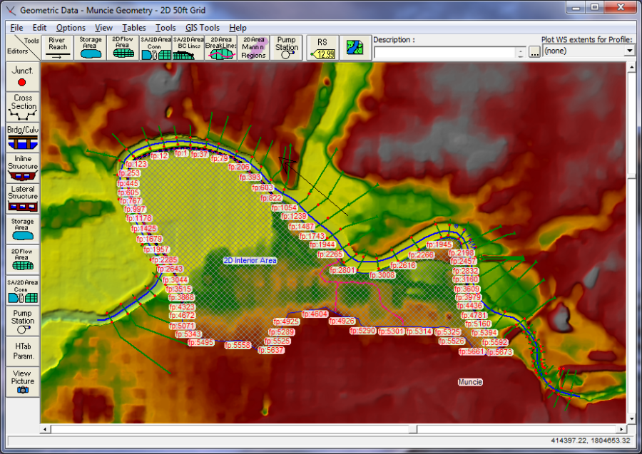
For this example, zoom into the upstream end of the river, which is on the right hand side of the schematic. At this location add a Lateral Structure that represents the levee in that region. When a Lateral Structure is added to the 1D River Reach, the user can select to link it to another 1D River Reach, a Storage Area, or a 2D flow area. If the user selects to link the Lateral Structure to a 2D flow area, then the stationing of the Lateral Structure will be linked to the 2D Area's face points automatically (this is analogous to the Lateral Structure automatically determining the location and intersection of the 1D cross sections). The connected levee is shown in Figure 3-24.
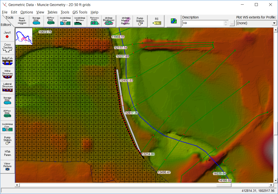
In this example, this Lateral Structure (levee) will be used to model flow going over the levee, as well as a levee breach that will be added later.
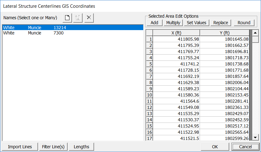
HEC-RAS has the option to have georeferenced lateral structures. Under the menu item labeled GIS Tools, there is now a table option called Lateral Structure Centerlines Table. User can use the Measure Tool to draw a line that would represent the lateral structure geospatial X and Y coordinates, then paste those coordinates into the Lateral Structure Centerline Table (This is optional). If a user inserts geospatial coordinates for a lateral structure, not only will it be drawn geospatially correct, but HEC-RAS will figure out how elements (1D cross sections and 2D Face Points) are connected to the lateral structure based on its spatial location. User's can also layout Lateral structures in HEC-RAS Mapper by editing the geometry layer, then the Lateral structure layer.
Note: if you put in a Geospatial centerline for a lateral structure, the length of the lateral structure weir/embankment stationing must be within 0.5% of the length of the centerline put in (i.e., they need to be consistent with each other in terms of length).
Users can use the Geometry Editor measuring tool option to draw the geospatial line that will represent the Lateral Structure, or they can import the geospatial information from an ESRI shapefile. Shown in Figure 3-25 is the Lateral Structure Centerlines Table.
To draw a geospatial line from within the Geometric Data editor, use the measuring tool option. This is accomplished by holding down the Cntrl key, then using the mouse pointer and the left mouse button to draw the line. Click the left mouse button to start the line, then move the mouse and continue to left click to add additional points in the line. As you are drawing the line, you can also right click the mouse to re-center the drawing within the Geometric Data editor. This is very helpful when you are zoomed in and need to continue the line to an area off of the screen. To finish the line, left click on the last point then release the Cntrl key. Once you release the Cntrl key, a window will appear as shown in Figure 3-26.
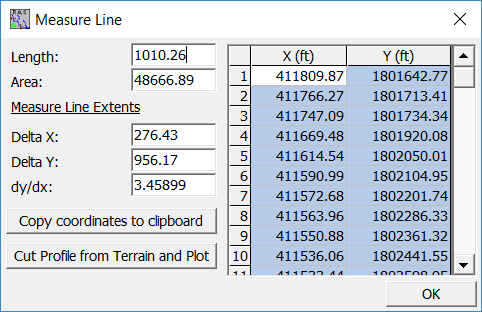
As shown in Figure 3-26, the measuring tool will show you the geospatial X and Y coordinates of the line in a table. To send these coordinates to the Windows Clipboard (so you can then paste them into the Lateral Structure Centerlines Table), simply press the button labeled: Copy GIS to Clipboard. These coordinates can be pasted into the Lateral Structure Centerline Table to georeferenced a lateral structure. The measuring tool window also shows you the length of the line; the area of a polygon if the first and last point were connected; Delta X; Delta Y; and dy/dx. Additionally you can plot the terrain data underneath that line by pressing the button labeled: Cut Profile from Terrain and Plot (This only works if you have a terrain data set in RAS Mapper and you have it associated with the currently opened Geometry file). This line can be used as a first cut for the user entered Weir Station and Elevation data for the Lateral Structure Weir profile. This is especially useful if the Lateral Structure is being used to represent the high ground barrier between the main channel (1D river reach) and overbank area (2D Flow Area).
The process of connecting a Lateral Structure to a 2D flow area is described below:
- Add the Lateral Structure as would normally be done in HEC-RAS (i.e., create the Lateral Structure; define the upstream River Station of the structure; enter the station/elevation points that represent the weir/embankment of the top of the structure; and add geospatial data for the lateral structure as described above).
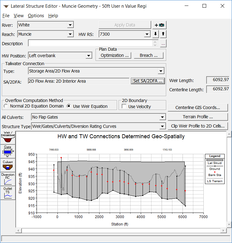
- For the Tailwater Connection option on the Lateral Structure editor, select the Type as Storage Area/2D Flow Area. Then from the SA/2D FA field, select the name of the 2D flow area to be connected to the lateral structure by pressing the Set SA/2DFA button and selecting the 2D flow area name. In this example the name of the 2D flow area is "2D Interior Area" (see Figure 3-27).
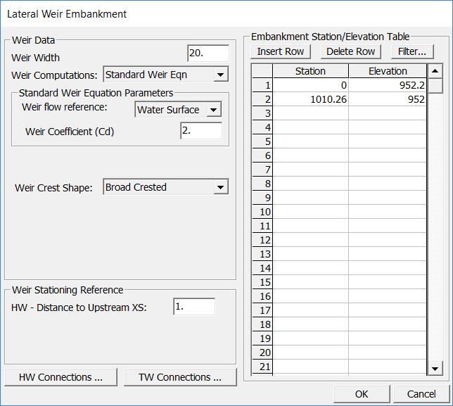
- Next, select the Weir/Embankment button on the left side of the graphic window. This will bring up the editor that will allow the user to define the top profile of the embankment, as well as determine how the lateral structure is connected to the 1D river cross sections (the headwater side of the structure), and to the 2D area face points (the tailwater side of the structure), as shown in Figure 3-28.

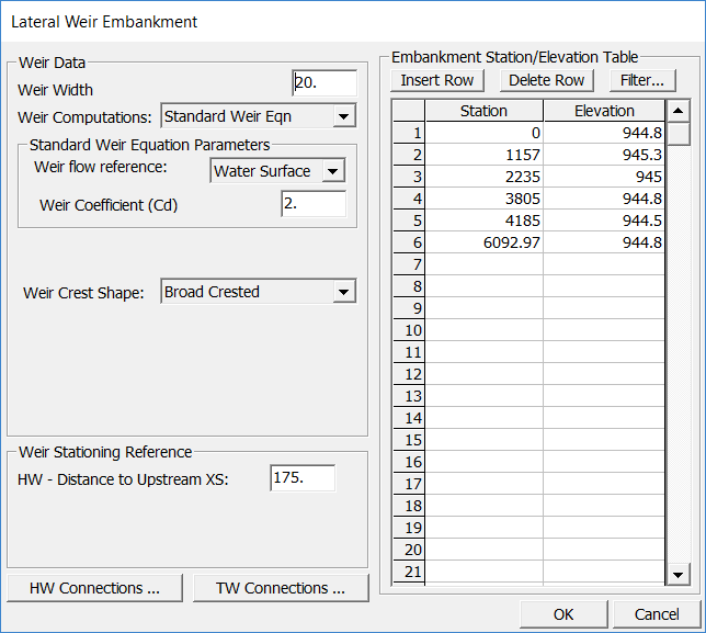
As shown in Figure 3-28, the user goes about the normal process of entering a Lateral Structure in HEC-RAS by entering the: weir width, weir coefficient, HW (Headwater) Distance to Upstream XS, and the Weir Station and Elevation points. This will define the top of the lateral structure (levee) profile.
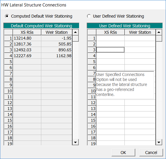
For the HW Connection to the 1D cross sections, the user can use the default, which is to have HEC-RAS compute the intersection of the 1D cross sections with the Lateral Structure based on the cross section overbank reach lengths (or based on the lateral structures geospatial data, if the user enters geospatial coordinates for the lateral structure) and the Lateral Structure weir profile stationing (see Chapter 6 of the HEC-RAS User's Manual, "Entering and Editing Lateral Structure Data" section, for more detailed discussion). Or the user can choose the option called User Defined Weir Stationing to enter their own intersection locations between the 1D cross sections and the Lateral Structure Weir Stationing. To view and/or edit the Headwater connection data, press the button labeled HW Connections from the Lateral Weir Embankment editor. When you do a window will appear as shown in Figure 3-29. In this example, the 1D river cross sections are being lined up with the Lateral Structure Weir Station automatically by HEC-RAS. This example also shows that geospatial data was entered for the Lateral Structure Centerline, so the option for the user to enter their own connections from the 1D cross sections to the Lateral Structure is not available.
For the Tailwater Connection to the 2D Flow Area, the user can select either the default (HEC-RAS will compute the connection between the Lateral Structure Weir stationing and the 2D Flow Area Face Points), or they can define their own connection between the Lateral Structure Weir station and the 2D Flow Area Face Points. To view and/or edit the Tailwater connection data, press the button labeled TW Connections from the Lateral Weir Embankment editor. When you do a window will appear as shown in Figure 3-30. In this example, the Lateral Structure Weir Station is automatically connected to the 2D Flow Area Face Points by HEC-RAS. This example also shows that geospatial data was entered for the Lateral Structure Centerline, so the option for the user to enter their own connections from the 2D Flow Area Face Points to the Lateral Structure Weir stationing is not available.

The last step is to make sure that the 2D flow area Face Points are correctly linked to the stationing of the Lateral Structure. The Tailwater linking is done automatically by HEC-RAS, but the user can override what it does (as described above). By default, the software will come up with the Tailwater Connection table set to Computed Default Weir Stationing. In this mode, HEC-RAS will automatically determine the connections between the lateral structure and the 2D flow area. This means HEC-RAS will find the 2D flow area face points that start at the upstream end of the structure and go along the structure to the downstream end. Generally, a lateral structure will not start exactly at a 2D flow area face point. So, HEC-RAS will pick the face point just upstream of the lateral structure to start the connection. This point will normally be given a negative weir stationing, meaning that it is actually upstream of the lateral structure by that distance. So the zero weir stationing is actually in between two face points. The second face point in the table will be the next point downstream and it will have a positive weir stationing. This stationing will represent how far the upstream end of the lateral weir is from that Face Point, along the length/stationing of the lateral weir.
If Geospatial coordinates are not entered for the Lateral Structure, the user has the option to enter the face points and Lateral Structure weir stationing by hand. This is done by selecting User Defined Weir Stationing from the Tailwater Connection window. Once the user has selected User Defined Weir Stationing they can enter/change/modify the table as they see fit. However, the user must remember not to skip any face points as previously discussed. To connect an HEC-RAS Lateral Structure to a 2D flow area by hand, the user enters face point numbers, from upstream to downstream, that will be linked to the Lateral Structures weir profile stationing. If the Lateral Structure does not begin at a face point, start with the face point that is just upstream of the beginning of the Lateral Structure. Also, continue entering Face Points until you have just gone past the end of the lateral structure. The Face Point numbers must be in the order that they are labeled on the 2D flow area boundary, starting upstream and going downstream.
Sometimes, the graphical length of the weir is shown longer or shorter than the true length. This occurs when the lateral structure is on the outside or inside of a bend, and the user has not entered any geospatial information for the Lateral Structure Centerline Table. When this occurs, the HEC-RAS automated Face Point connections will be adjusted such that the Lateral Structure weir stationing lines up with the correct Face Points. This is done by figuring out the total length along the 2D flow area, from Face Point to Face Point, then proportioning those lengths based on the total Length of the Lateral Structure divided by the total length along the 2D flow area Face Points. If the user chooses to enter the Tailwater connection using User Defined Weir Stationing, then the user has to determine the intersections on their own. One way to do this is to measure the lengths along the face points, and then use Excel to reduce the lengths to equal the true structure length, by multiplying the computed face point lengths by the ratio of the true structure length divided by the graphical length of the structure.
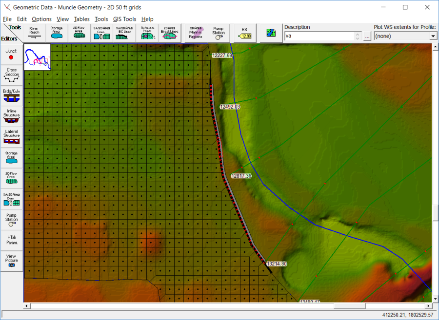
Once the user has entered all of the data for the Lateral structure, including the links to the 2D flow area, press the OK button to close the Lateral Weir Embankment editor, then close the Lateral Structure editor (unless the user needs/want to add gates, culverts, rating curves, etc… to further define the details of the lateral structure). The HEC-RAS Geometric editor will now show a thick black line along the 2D Area Face Points, to show you where the Lateral Structure is connected to the 2D flow area (see Figure 3-35). If this black line does not follow all of the appropriate Face Points from the 2D flow area, then there is a mistake in the 2D flow area connection table. So the thick black line can be used as a guide to help identify if the Lateral Structure is connected correctly to the 2D flow area. The Black line represents the 2D Faces that are connected to the lateral structure. The Black line will always start and stop at the beginning or end of a 2D Face (Face Point). On top of the black line is a Red dashed line, the Red line represents where HEC-RAS has linked the lateral structure to the 2D Flow Area boundary. The Red line can start and stop in the middle of a 2D Face. The Red Line shows the user the exact location of how the 2D area is connected to the Lateral Structure.
Shown in Figure 3-31 is how the Lateral structure will look when geospatial data has been entered for the centerline of the structure.
For this example a breach location/data has also been added for the analysis of this upper levee. Shown in Figure 3-32 is the Levee (Lateral Structure) Breach Data editor with the data for this levee.
For this specific example, a second additional lateral structure at the lower end of the 2D flow area will be added. This Lateral Structure will be used to model flow that ponds on the inside of the protected area, then flows back over the top of the Levee (Lateral Structure) into the 1D river system. See Figure 3-33 for the extents of this downstream Levee.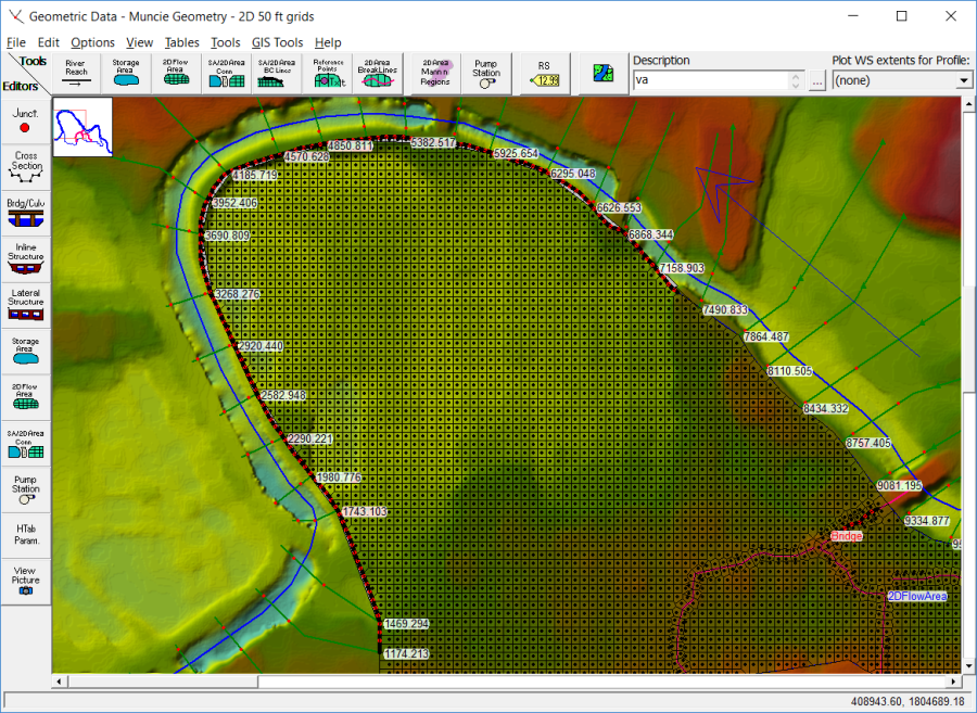
The downstream Lateral Structure in this example starts at River Station 7300, and goes along the entire downstream boundary of the protected area, tying back into high ground at the downstream end. The Lateral Structure editor for this Levee is shown in Figure 3-34.
Shown in Figure 3-35, is the Weir Embankment editor, with the data for the Lateral Structure stationing and elevations, as well as access to the Lateral Structure linking to the 1D cross sections (HW Connections) and the 2D flow area Face Points (TW Connections).
Lateral Structure Computations
There are two computation methods when using a Lateral Structure to connect a 2D Flow Area to a 1D River Reach: Normal 2D Equation Domain and the Weir Equation.
- The Normal 2D Equation Domain uses a stage boundary on the 2D area to compute flow using the 2D solver for each face along the lateral structure. When the WSE on the 1D side is lower than the WSE on the 2D side at a given face, HEC-RAS computes a critical depth by taking two-thirds of the hydraulic depth of the 2D WSE and will use the higher of this critical depth WSE or the 1D WSE for the tailwater.
- The Weir Equation aggregates the cell faces along the lateral structure to create a weir profile. The energy grade line for the higher of the 2D and 1D water surface surfaces is used to compute flow using the weir equation.
The Lateral Structure computations have been improved over time.
For version 6.5 and 6.6, if the WSE in the 1D river is below the lateral structure, there would be no flow (at a given face) even when the WSE was high enough in the 2D that there should be flow leaving the 2D area and entering the river.
For prior versions where the 1D river WSE was above the structure but below the 2D critical depth approximation, it is computing flow, but this flow is incorrectly based on a stage below critical depth. The area of this stage outflow is too small, reducing the flow. On the other hand, the energy gradients are probably too steep increasing the flow. While these will tend to offset, the hydraulics may not be accurate.
For version 6.4.1 and prior, when the 1D WSE was below the structure, it is computing a flow but the hydraulics are probably not accurate.
Lateral Structure Weir Coefficients
In general, Lateral Structure weir coefficients should be lower than typical values used for inline weirs. Additionally, when a lateral structure (i.e., weir equation) is being used to transfer flow from the river (1D region) to the floodplain (2D flow area), then the weir coefficients that are used need to be very low, or too much flow will be transferred. Below is a table of rough guidelines for Lateral weir coefficients under different conditions:
Table 3-1. Lateral Weir Coefficients
What is being modeled with the Lateral Structure | Description | Range of Weir Coefficients |
|---|---|---|
Levee/Roadway – 3ft or higher above natural ground | Broad crested weir shape, flow over levee/road acts like weir flow | 1.5 to 2.6 (2.0 default) |
Levee/Roadway – 1 to 3 ft elevated above ground | Broad crested weir shape, flow over levee/road acts like weir flow, but becomes submerged easily. | 1.0 to 2.0 |
Natural high ground barrier – 1 to 3 ft high | Does not really act like a weir, but water must flow over high ground to get into 2D flow area. Flow does not pass through critical depth | 0.5 to 1.0 |
Non elevated overbank terrain. Lat Structure not elevated above ground | Overland flow escaping the main river. | 0.2 to 0.5 |
The biggest problem HEC-RAS users have when interfacing 1D river reaches with 2D flow areas is using a weir coefficient that is too high for the situation being modeled. If the lateral structure is really just an overland flow interface between the 1D river and the 2D floodplain, then a weir coefficient in the range of 0.2 to 1.0 should be used to get the right flow transfer and keep the model stable. However, weir coefficients should be calibrated to produce reasonable results whenever possible.
A second issue is weir submergence. When a lateral structure gets highly submerged, HEC-RAS uses a weir submergence curve to compute the flow reduction over the weir. The curve is very steep (i.e., the flow reduction changes dramatically) between 95% and 100% submergence. This can cause oscillations and possible model stability issues. To reduce these oscillations, user can have HEC-RAS use a milder loping submergence curve by going to the 1D "Computational Options and Tolerances" and setting the field labeled "Weir flow submergence decay exponent" to 3.0.
Directly Connecting an Upstream River Reach to a Downstream 2D Flow Area
Users can connect a 1D River Reach directly to a 2D flow area. When this type of boundary condition is used, the last cross section of the 1D River Reach must be lined up with the upstream boundary of the 2D flow area (i.e., the last cross section of the 1D reach is directly linked to the boundary of the 2D area, so they need to be at the same exact location). See the example shown in Figure 3-36.
For this type of boundary condition, the 1D River Reach passes flow each time step to the 2D flow area, while the stage in the cross section is based on the water surface elevation in the 2D cells that it is connected to. Flow is distributed to the 2D cells based on the conveyance distribution in the cross section, and the stationing of the cells linked to the cross section. The computed stage for the 1D cross section is based on computing a conveyance weighted stage from the connected boundary cells in the 2D flow area, and then forcing that stage on the 1D cross section each time step.
This type of boundary condition should only be placed in areas where the flow and stage are highly one-dimensional in nature. If the flow is not highly one-dimensional, you may run in to model stability issues with this type of boundary condition. User's can try turning on the option to allow the program to iterate back and forth between the 1D and the 2D computations during each time step, until the computed flow and stage at the boundary connection converges within a user specified tolerance. This may not solve the issue for areas that are highly two-dimensional (i.e., the water surface varies significantly). If the flow is highly one dimensional, 1D to 2D iterations are generally not necessary for this type of boundary condition.
To connect a 1D river reach to a 2D flow area, do the following:
- Draw the 2D area polygon such that the outer boundary at the upstream end is right on top of the last cross section of the 1D River Reach.
- Go to the Edit menu of the Geometric Data editor, and turn on the Option to Move Points/Objects.
- Move the last point of the stream centerline inside of the 2D flow area. The software will ask you if you want to connect the 1D River Reach to the 2D flow area. Select Yes.
This type of connection between a 1D cross section and a 2D area requires the following to be true:
- The location for this type of connection should be placed where the flow is highly one-dimensional (water surface is relatively horizontal and flow lines are perpendicular to the 1D cross section.
- The 1D cross section is exactly on top of the boundary of the 2D area that it is connected too.
- The terrain defining the 1D cross section must be exactly the same as the terrain along the boundary of the 2D flow area where it is connected to the 1D cross section.
- The Manning's roughness coefficients must be exactly the same spatially along the cross section and the 2D flow area boundary that it is connected too.
Once the 2D flow area and the 1D River Reach are connected, the software will draw a black line along the 2D flow area cells outer boundary to show the user how it is connected. The Black line represents the 2D cell Faces that the 1D cross section is connected to. A red line is drawn on top of the black line. The red line represents what HEC-RAS thinks is the exact location of where the 1D cross section starts and stops along the 2D Flow Area boundary. The red line is what HEC-RAS is using to figure out what portion of the 1D cross section corresponds to the 2D Flow Area Faces. That is all that needs to be done for the connection.
When a 1D River Reach is connected to a 2D area, the user will need to define the initial conditions for the 1D Reach and the 2D area. Initial conditions for the 2D Area can be: set to a single water elevation; set using a "Restart" file from a previous run; or the user can select to run a warm-up period at the beginning of the run, in which flow and stage boundaries connected to the 2D area will be applied slowly over time.
The 2D unsteady flow solver can handle "wetting" and "drying" of cells. However, the original finite difference 1D unsteady flow solver cannot handle "dry" cross sections. Therefore, a "wet" water surface at the 1D/2D boundary must be established at the beginning of the run and maintained during the simulation. If a restart file is not used, then HEC-RAS will compute the starting water surfaces in two distinct parts. The first part is the "initial condition" phase.
For the initial condition phase, water surfaces are determined for any 2D areas that start wet and the initial backwater is determined for all 1D reaches. Every 2D area that has a direct connection to a 1D reach must have enough water in it to provide a water surface at any and all of the 1D boundary connections. The user can specify a starting 2D water surface and/or use the 2D Initial Conditions Ramp Up option (This is highly recommended). To set the 2D Initial Conditions Ramp Up option, go to the Unsteady Flow Analysis window, then Select Calculation Options and Tolerances from the Options menu. Select the 2D Flow Options Tab. Enter a time in hours for each of the 2D flow areas in the filed labeled Initial Conditions Time (hrs). This is the time each 2D flow area will run on its own at the beginning in order to establish a good initial conditions within that 2D Flow Area.
During this phase, the program may cycle between 2D areas and 1D reaches in order to determine the flows and water surfaces at the boundaries. If the upstream end of a 1D reach is connected directly to a 2D area and the user has specified an initial flow for this reach, then the program will use that flow during the initial conditions. If an initial flow is not specified, then the program will attempt to determine this flow automatically. If the downstream end of a 1D reach is connected, then there is nothing for the user to specify. The program will try to determine the water surface in the 2D area first which will allow for a stage boundary for the 1D reach. If this is not possible, a critical depth boundary may be initially used.
The second part of determining the starting water surfaces is the optional warm-up period. This is the same warm-up period that 1D has always had except that it now also includes the 2D areas. As explained above, there must be a valid water surface at the 1D/2D boundaries before the warm-up period and/or the main simulation starts.
Directly Connecting an Upstream 2D Flow Area to a Downstream River Reach
Users can directly connect an upstream 2D flow area to a downstream 1D River Reach. When this type of boundary condition is used, the first cross section of the 1D River Reach must be lined up with the downstream boundary of the 2D flow area (i.e., the first cross section of the 1D reach is directly linked to the downstream boundary of the 2D area, so they need to be at the same exact location). See the example shown in Figure 3-37.
For this type of boundary condition, the 2D flow area passes flow each time step to the 1D river reach, while the stage in the 2D flow area is based on the stage in the 1D cross section that it is connected too. Flow is passed to the 1D section by adding all of the flows leaving the 2D cells at the boundary for each time step. The stage for the 2D flow area downstream boundary is set to the computed stage of the 1D cross section each time step.
This type of boundary condition should only be placed in areas where the flow and stage are highly one-dimensional in nature. If the flow is not highly one-dimensional, the user will need to turn on the option to allow the program to iterate back and forth between the 1D and the 2D computations during each time step, until the computed flow and stage at the boundary connection does not change within a user specified tolerance. Even if the flow is highly one-dimensional, 1D to 2D iterations may be necessary for this type of boundary condition, depending on how quickly the flow and stage are changing, compared to the user selected computation interval.
To connect an upstream 2D flow area directly to a downstream 1D River Reach, do the following:
- Draw the 2D flow area polygon such that the outer boundary at the downstream end is right on top of the first cross section of the 1D river reach.
- Go to the Edit menu of the Geometric Data editor, and turn on the Option to Move Points/Objects.
- Move the first point of the stream centerline inside of the 2D flow area. The software will ask you if you want to connect the 1D River Reach to the 2D flow area. Select Yes.
This type of connection between a 2D area and a 1D cross section requires the following to be true:
- The location for this type of connection should be placed where the flow is highly one-dimensional (water surface is relatively horizontal and flow lines are perpendicular to the 1D cross section.
- The 1D cross section is exactly on top of the boundary of the 2D area that it is connected too.
- The terrain defining the 1D cross section must be exactly the same as the terrain along the boundary of the 2D flow area where it is connected to the 1D cross section.
- The Manning's roughness coefficients must be exactly the same spatially along the cross section and the 2D flow area boundary that it is connected too.
Once the 2D flow area and the 1D River Reach are connected, the software will draw a black line along the 2D flow area cells outer boundary to show the user how it is connected. The Black line represents the 2D cell Faces that the 1D cross section is connected to. A red line is drawn on top of the black line. The red line represents what HEC-RAS thinks is the exact location of where the 1D cross section starts and stops along the 2D Flow Area boundary. The red line is what HEC-RAS is using to figure out what portion of the 1D cross section corresponds to the 2D Flow Area Faces. That is all that needs to be done for the connection.
For the initial condition phase, water surfaces are determined for any 2D areas that start wet and the initial backwater is determined for all 1D reaches. Every 2D area that has a direct connection to a 1D reach must have enough water in it to provide a water surface at any and all of the 1D boundary connections. The user can specify a starting 2D water surface and/or use the 2D Initial Conditions Ramp Up option (This is highly recommended). To set the 2D Initial Conditions Ramp Up option, go to the Unsteady Flow Analysis window, then Select Calculation Options and Tolerances from the Options menu. Select the 2D Flow Options Tab. Enter a time in hours for each of the 2D flow areas in the filed labeled Initial Conditions Time (hrs). This is the time each 2D flow area will run on its own at the beginning in order to establish a good initial conditions within that 2D Flow Area.
Connecting a 2D Flow Area to a Storage Area using a Hydraulic Structure
A 2D flow area can be directly connected to Storage Area by using a hydraulic structure called a Storage Area/2D flow area Hydraulic Connector (SA/2D Area Conn). See the example in Figure 3-38 below.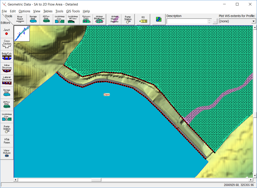
In the example shown in Figure 3-38, the Storage Area is upstream of the 2D flow area, so the positive flow direction is from the storage area to the 2D flow area. Therefore, when defining the hydraulic structure that connects the two areas, the Storage Area will be considered the Headwater side, and the 2D flow area will be considered the Tailwater side. This can also be done the other way, in which the 2D flow area is on the upstream side (Headwater) and the Storage Area is on the downstream side (Tailwater). For the example shown in Figure 3-38, a Storage Area is being used to represent a reservoir pool. The hydraulic connection between the Storage Area and the 2D flow area is a dam (SA/2D Area Hydraulic Connection) in this example. The 2D flow area is being used to model the hydraulics of the flow downstream of the dam.
To hydraulically connect a Storage Area to a 2D flow area, do the following:
- Draw the storage area polygon right up to the edge of the hydraulic structure. This can be as close to the hydraulic structure as desired for mapping purposes.
- Draw the outer boundary of the 2D flow area right up to the other side of the hydraulic structure. This can also be very close to the hydraulic structure. However, keep in mind that the computed water surface elevations of the boundary cells of the 2D area will be used in the hydraulic calculations over/through the structure (don't put very small cells down the face of a steep embankment). Generally, the water surface computed for the 2D cells should represent what the user wants for the water surface in the hydraulic calculations of flow over and through the hydraulic structure. That is, don't put very small cells down the face of a steep embankment because the small boundary cells may end up with a transitional water surface that is between the "headwater" and the "tailwater" surfaces. If this happens, the accuracy of the hydraulic computations across the structure may be reduced.
- Select the drawing tool at the top of the Geometric Data editor labeled SA/2D Area Conn. Then draw a line directly down the center of the hydraulic structure that will be used to connect the two flow areas. Draw this line from left to right looking downstream. This is how HEC-RAS will detect what is upstream (headwater) and what is downstream (tailwater). The interface will ask for a label to define the hydraulic structure. See the red line shown in Figure 3-38.
- Next, select the Storage Area/ 2D flow area Hydraulic Connection (SA/2D Area Conn) editor on the left panel of the Geometric Data editor. This will bring up the editor shown in Figure 3-39.
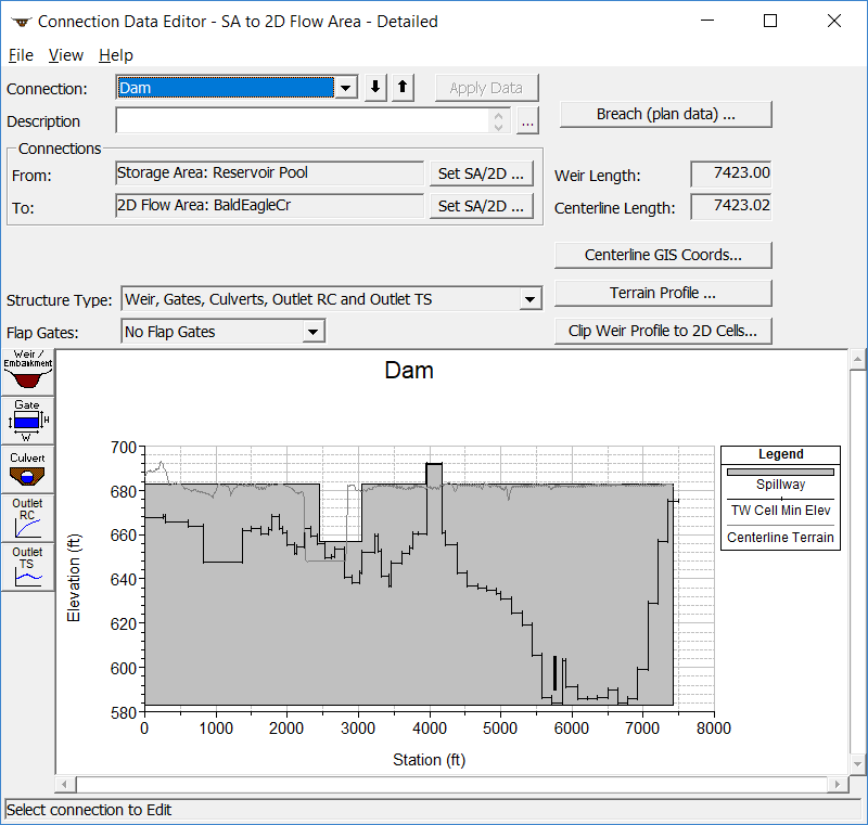
- On the SA/2D Area Conn editor set the From and To by selecting the buttons labeled Set SA/2D Area. For this example, the storage area labeled "Reservoir Pool" is the From element, and the 2D flow area labeled "BaldEagleCr" is the To element.
- Enter all the hydraulic structure information for the connection. This will consist of a Weir/Embankment profile, and any additional hydraulic outlets, such as culverts, gates, etc… In the example shown in Figure 3-39, there is an embankment with an emergency spillway defined, and there are also two low flow gates defined.
Geospatial coordinates can be entered can be entered for any of the outlet types avasilable in the SA/2D Area Connection editor (ie. Culvert, gates, rating curves, and time series outlet). This will allow the user to specify a location within the 2D area that you want that specific outlet to connect to, such as an interior cell instead of one of the boundary cells.
This is all that is needed for this type of hydraulic connection. HEC-RAS automatically computes the stationing along the centerline drawn for the hydraulic structure, and then lines it up with the outer boundary of the 2D flow area based on their spatial location. The connection to the Storage Area is very simple, since it can only have a single water surface elevation inside the storage area each time step.
Connecting a 2D Flow Area to another 2D Flow Area using a Hydraulic Structure
2D flow areas can be directly connected to other 2D flow areas by using a hydraulic structure called a Storage Area/ 2D flow area Hydraulic Connector (SA/2D Area Conn). See the example below in Figure 3-40.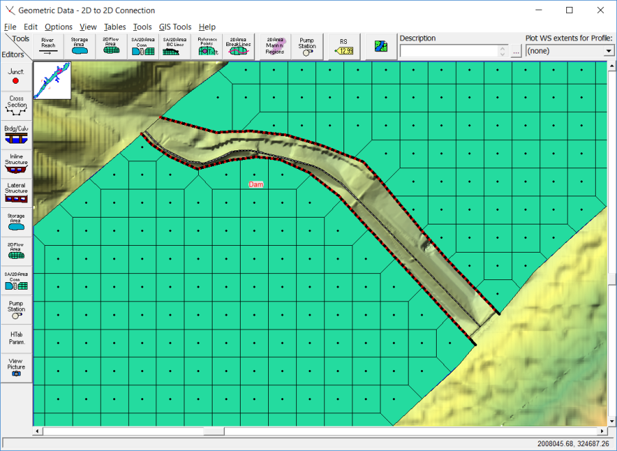
In the example shown in Figure 3-40, there is a 2D flow area upstream of another 2D flow area, so the positive flow direction is from the upstream 2D flow area to the downstream 2D flow area. When defining the hydraulic structure that connects the two areas, the upstream 2D flow area will be considered the headwater side, and the downstream 2D flow area will be considered the tailwater side. The hydraulic connection between the two 2D flow areas is a dam in this example. The downstream 2D flow area is being used to model the hydraulics of the flow downstream of the dam.
To hydraulically connect one 2D flow area to another 2D flow area, do the following:
- Draw the upstream 2D flow area polygon right up to the edge of the hydraulic structure. This should be relatively close to the hydraulic structure for mapping purposes.
- Draw the outer boundary of the downstream 2D flow area right up to the other side of the hydraulic structure. This can also be very close to the hydraulic structure, however, keep in mind that the computed water surface elevations of the boundary cells of the 2D area will be used in the hydraulic calculations over/through the structure (i.e., don't put very small cells down the face of a steep embankment). Generally, the 2D cells computed water surfaces should represent what the user wants to be used in the hydraulic calculations of flow over and through the hydraulic structure.
- Select the drawing tool at the top of the Geometric Data editor labeled SA/2D Area Conn. Then draw a line directly down the center of the hydraulic structure that will be used to connect the two flow areas. The interface will ask the user for a label to define the hydraulic structure. See the red line shown in Figure 3-40.
- Next, select the Storage Area/ 2D flow area Hydraulic Connection (SA/2D Area Conn) editor on the left panel of the Geometric Data Editor. This will bring up the editor shown in Figure 3-41.
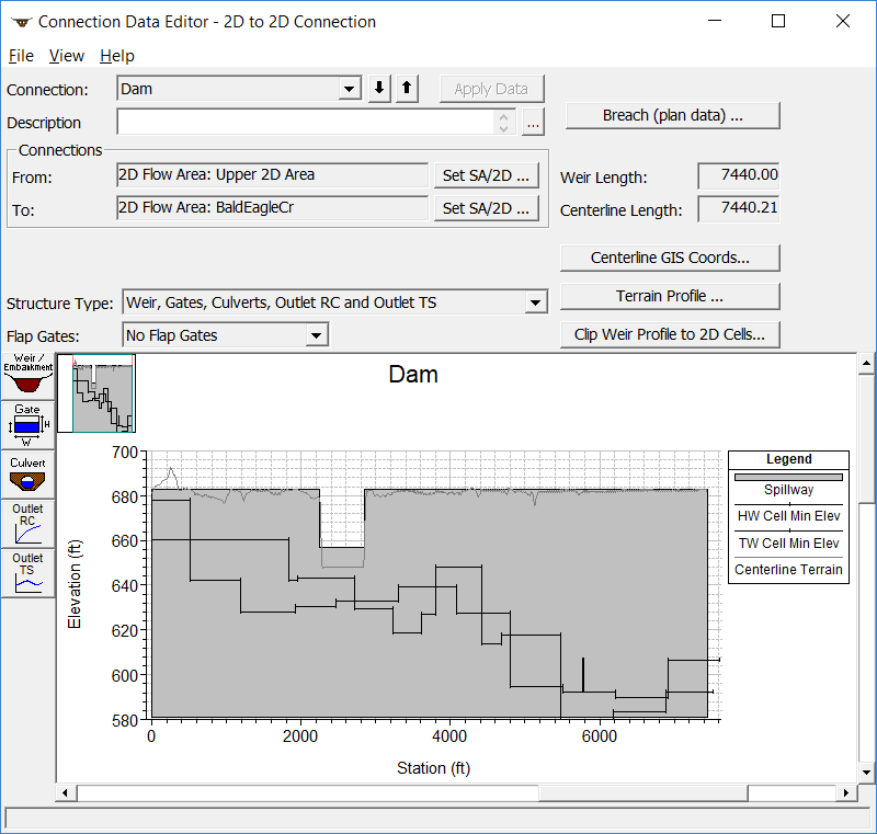
- On the SA/2D Area Conn editor set the From and To by selecting the buttons labeled Set SA/2D Area. In this example the upstream 2D flow area labeled "Upper 2D Area" is the From element, and the 2D flow area labeled "BaldEagleCr" is the To element.
- Enter all the hydraulic structure information for the connection. This will consist of a weir/embankment profile, and any additional hydraulic outlets, such as culverts, gates, etc… In the example shown in Figure 3-45, there is an embankment with an emergency spillway defined, and there are also two low flow gates defined.
This is all that is needed for this type of hydraulic connection. HEC-RAS automatically figures out the stationing along the centerline drawn for the hydraulic structure, and then lines it up with the outer boundary of the upstream and downstream 2D flow areas based on their spatial location.
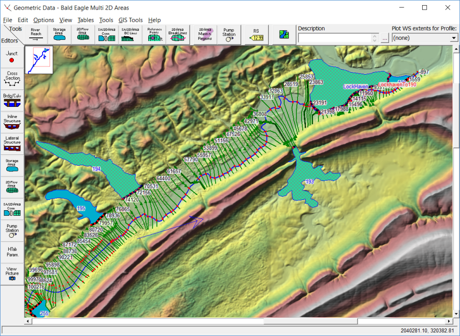
Multiple 2D Flow Areas in a Single Geometry File
HEC-RAS has the ability to have any number (within the computer's memory limitations) of separate 2D flow areas within the same geometry file. Multiple 2D flow areas can be added in the same way as storage areas. Hydraulic connections can be made from 2D flow areas to 1D Elements, as well as between 2D flow areas. See the example in Figure 3-42.