Download PDF
Download page Hydraulic Structures Inside of 2D Flow Areas.
Hydraulic Structures Inside of 2D Flow Areas
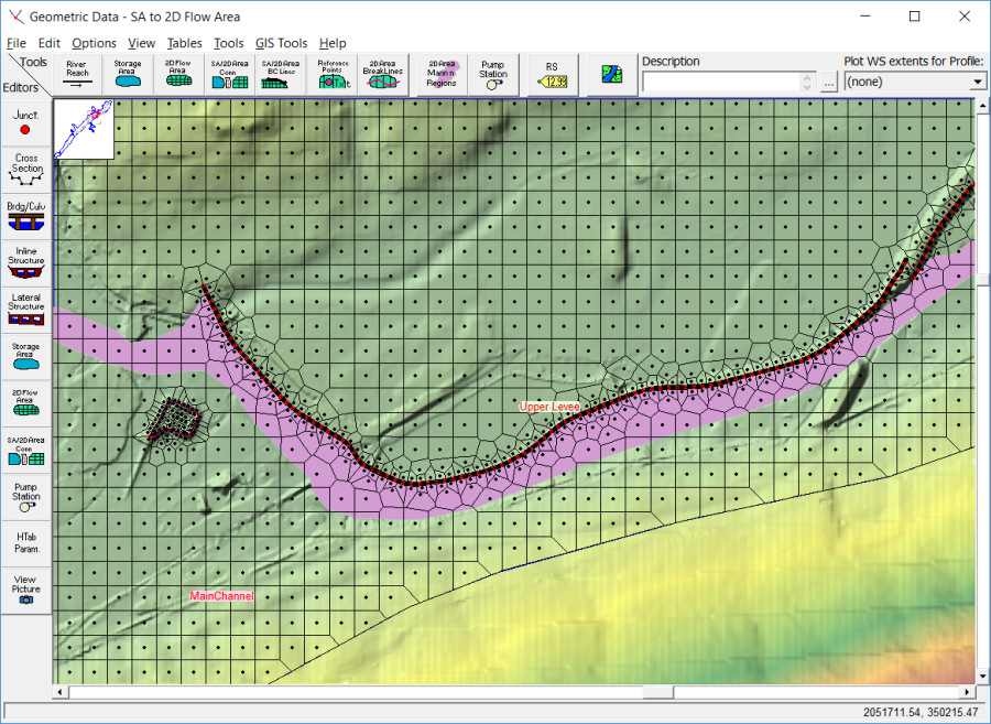
The SA/2D Area Conn option ![]() does more than connect storage areas and 2D areas. You can also use it to add a hydraulic structure in the middle of a single 2D flow area (see Figure below). The hydraulic structure aligns cells along the structure and can control the cell size along the structure, just like a break line. 2D Area Connections can be used to model a Weir with Gates and Culverts or as a Bridge.
does more than connect storage areas and 2D areas. You can also use it to add a hydraulic structure in the middle of a single 2D flow area (see Figure below). The hydraulic structure aligns cells along the structure and can control the cell size along the structure, just like a break line. 2D Area Connections can be used to model a Weir with Gates and Culverts or as a Bridge.
The SA/2D Area Conn has multiple Structure Type options: 1) Weir, Gates, Culverts, Outlet RC and Outlet TS; 2) Linear Routing option (The Linear Routing option is for storage areas only, not 2D Flow Areas); 3) Bridge (1D Family of RCs); and 4) Bridge (2D Pressure and Overtopping).
Weir, Gates, Culverts, Outlet RC and Outlet TS
The SA/2D Hydraulic Connection can be used to model multiple kinds of structures inside of a 2D Flow Area. Flow going over top of the structure can be modeled with either a weir equation, or the full 2D equations. Additionally there are options to add gates, culverts, rating curves, and time series of flows for independent outlets. Any combination of these outlet types can be used. Additionally, users can now specify an X and Y geospatial coordinates for the upstream and downstream ends of each hydraulic outlet (culverts, gates, rating curves, and time series outlets).
To add a hydraulic structure inside of a 2D flow area, do the following:
Try Adding 2D Structures in Mapper
2D structures can be directly added in RAS Mapper; however, will will need to complete the data from the Geometric Schematic.
- First, select the Drawing tool at the top of the Geometric Data editor labeled SA/2D Area Conn. Then draw a line directly down the center of the hydraulic structure (Note: this line must be drawn from left to right, while looking from what is considered to be upstream to downstream. This is how the program figures out what is considered to be the headwater side and the tailwater side.). This line will represent the hydraulic structure that will be used to connect the 2D flow areas cells on one side of it to the other side of it. The interface will ask for a label to define the name of the hydraulic structure. This structure centerline can also be drawn from RAS Mapper.
- Next, modify the 2D flow area mesh so that the faces of the cells go along the centerline of the top of the hydraulic structure. To do this, left-click on the Hydraulic structure centerline and select the Edit Internal Connection (Break Line) Cell Spacing option. A window will appear in which it will allow the user to enter a Minimum and Maximum cell spacing to be used for creating cells along the centerline of the hydraulic structure. By default it will use the nominal cell size for spacing cells along the hydraulic structure centerline, however, the user can change the cell spacing along the structure to get more detail along the hydraulic structure. This step is optional, but generally a good idea to establish cells along the structure with an appropriate size.
- Next, left-click on the hydraulic structure centerline and select the option called Enforce Internal Connection as Break Line in 2D Flow Area. When this option is selected, the software will use the structure centerline and the cell spacing information to create cells along the centerline of the structure that have faces exactly along the centerline. This is a necessary step in order to get the 2D mesh correctly developed for incorporating the hydraulic structure data (Station-elevation data; culverts, gates, breaches, etc…)
The 2D Connection must span at least 1 cell face. A runtime error message will be listed with the structure name and the computations will stop, if the structure is not at least 1 cell wide.
For example, as shown in the figure above, a levee is being modeled inside of a single 2D flow area as a hydraulic structure. The 2D flow area mesh was modified to have cells on both sides of the levee lined up on top of the levee. This requires adding small enough cell spacing along the hydraulic structure centerline to get the correct detail. However, you do not want the cells to be so small that you have cells going down the levee embankment, such that these cells would be very steep. Steep cells on the back side of a levee could cause the model to have stability issues when flow overtops the levee (i.e., the flow may appear to be going over a water fall). Therefore, make the cells large enough to encompass the levee embankment slope and a little of the area away from the toe of the levee.
- Next, select the Storage Area/ 2D flow area Hydraulic Connection (SA/2D Area Conn) editor on the left panel of the Geometric Data Editor. This will bring up the 2D Connection editor shown in the figure below.
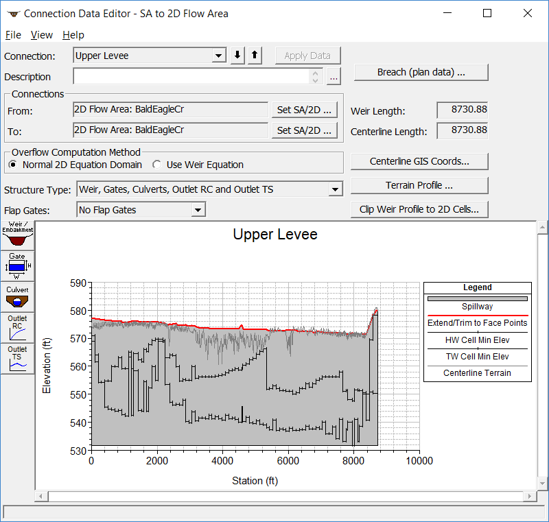
If the structure being modeled is high ground (as shown in the layout above), choose the Weir, Gates, Culverts, Outlet RC and Outlet TS structure type. The user can define station elevation data for the structure that is the same or higher than the natural ground using the Weir/Embankment Editor. Additionally, culverts, gated openings, rating curves, and time series outlets can be added into the hydraulic structure. The user entered weir line (station/elevation data), culverts, and gate openings, are not allowed to be lower than the minimum elevation of the cells they are connected to. However, a breach minimum elevation can go lower than the cells it is connected too (you will get a warning about this when you do it though). If a breach goes lower than the cells it is connected too, HEC-RAS will automatically lower the cell elevations (both upstream and downstream) dynamically as the breach is eroding down below the ground elevations. However, it will only lower the cells immediately next to the structure centerline on both sides.
The editor shows two black lines that represent the minimum elevations of the cells on each side of the internal hydraulic structure. These lines show the user both the elevation and stationing of how the hydraulic structure is connected to the 2D cells on each side of the structure. Users can click on any of these lines and get the cell number of the connection, as well as the stationing (stationing along the hydraulic structure) and elevation of the cell. Additionally the cell will be highlighted on the geometric data editor, so you can see where that cell lives spatially.
The user has the option for flow going over the top of the structure (Overflow Computation Method) to be computed by either the Weir Equation or the Normal 2D Equation Domain. If Weir Equation is chosen, all flow over the top of the hydraulic structure is computed with the weir equation. If Normal 2D Equation Domain is selected, the flow over the top of the structure is computed as normal 2D Flow between cells. In either case, the flow through the culverts and gates is computed separately and linked between the cells on each side of the culvert or gate. For a highly submerged structure, where the flow is not behaving like weir flow, the 2D equation will generally give better results, but the 2D equation is not as appropriate for traditional weir flow. The chart below describes the main differences and applications of these two methods (for more on this algorithm choice and best practices for these internal structures see the User Guide on Modeling 2D Weirs):
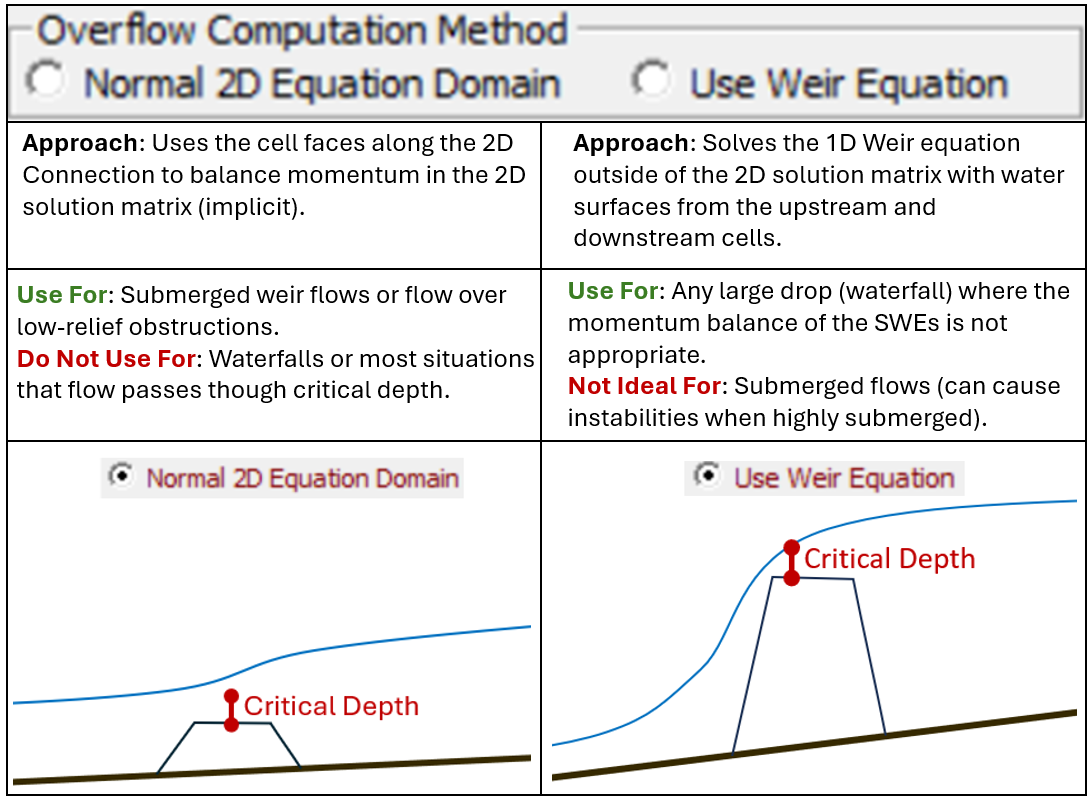
Warning: The "Normal 2D Equation Domain" option should NOT be used if the height of the structure is high, such that the water flowing over the structure will go into free fall (like a waterfall). The 2D equations cannot be solved in a stable solution through a waterfall. For this situation the user will need to use the "Weir Equation" option. We plan to investigate having the program automatically switch between the weir equation and the 2D equation based on the flow condition.
To enter the structure embankment data, select the Weir/Embankment button. The embankment editor will come up, and the user can enter station elevation data that is either the same as the ground profile, or they can enter elevations that are higher than the ground profile in order to represent a structure that is not accurately represented by the terrain data.
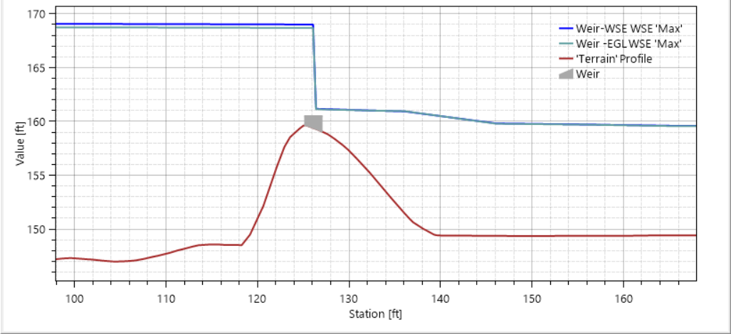
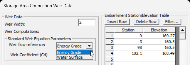
If modeling the structure using the Weir Equation, there is an option to compute weir flow based on either the upstream Water Surface Elevation or using the upstream Energy Grade Line. (The Energy Grade option was added in HEC-RAS 6.7). The computation option is available from the Weir/Embankment editor, as shown below.
An example profile plot comparing the water surface elevation using Water Surface with the Energy Grade for the headwater reference elevation is shown below. The water surface is higher for computation using the Water Surface as the reference elevation. The difference in computed water surface will be more dramatic for models with high velocities upstream of the weir.