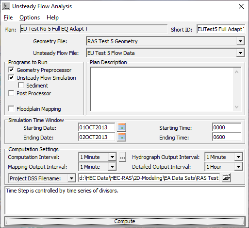
To run the model, open the Unsteady Flow Analysis window. Make a Plan by selecting the geometry that contains the combined 1D and 2D data, select an unsteady-flow file for the event to run, and give the Plan a Title and a Short ID. Set the following items: which Programs to Run; the Simulation Time Window; and all of the Computational Settings. Then press the Compute button to begin the run. (The window should look similar to Figure 5-5). If the 2D flow area pre-processor has not been previously computed (from RAS Mapper) then the pre-processor will compute automatically at the beginning of the unsteady flow process.
Under the Programs to Run area, there is a check box for Floodplain Mapping. If a terrain data set has been imported using RAS Mapper, associated with the relevant geometry files, and stored maps staged for generation, this option will automatically create those stored maps following a successful compute. This option is not required for flood mapping. The Floodplain Mapping option is off by default because the user can perform Dynamic Flood Mapping and create Static Flood Maps (e.g., stored Depth grids) from RAS Mapper after the computations have been completed (this is the suggested workflow). The main purpose of this option is to automate the process of computing an inundation map (e.g., Depth grid) for use in CWMS or HEC-WAT. In general, this option will most likely not be used when running HEC-RAS in a standalone mode.
The post processor option provides additional (and detailed) output for 1D areas and it is only applicable for 1D data sets and mixed 1D/2D data sets. The 2D output is generated during the unsteady flow run.
Under the Computational Settings area, there is a feature called Mapping Output Interval. This feature allows users to set a mapping interval that will be used in RAS Mapper for creating Dynamic Maps (computed on-the-fly in memory, and not stored to disk), as well as for performing animations of the flood maps. When the user selects a specific interval (e.g., 1-hr), a limited set of hydraulic output variables are written to a binary (HDF5) output file for all Cross Sections, Storage Areas, and 2D Flow areas. Additionally, the maximum and minimum values that were computed at all locations during the run are also written to this file. This file is then used by RAS Mapper to perform dynamic mapping of the results. There are some additional Mapping Output/HDF5 options under the Options menu. From the Option menu, point to Output Options and select HDF5 Write Parameters from the submenu.

Once the user presses the Compute button, the unsteady-flow computational engines will begin to run. This process consists of running the: 2D Geometry Pre-Processor (only if necessary), 1D Geometry Pre-Processor, Unsteady-Flow computations (combined 1D/2D), the 1D Post-Processor, and finally the Floodplain Mapping process (if it was turned on).
.