Download PDF
Download page 3D Perspective Plots.
3D Perspective Plots
Another type of graphic available to the user is the 3D Perspective Plot. The 3D plot is a 3-dimensional plot of the terrain on the computed results (Depth, water surface, velocity, etc.).
The HEC-RAS 3D Viewer was developed to help engineers convey hydraulic modeling results to decision-makers. The HEC-RAS 3D Viewer is accessed from either the HEC-RAS program or inside RAS Mapper. The 3D Viewer provides a three-dimensional visualization of HEC-RAS simulation results and terrain data. To access the 3D Viewer through the HEC-RAS program interface, go to View | 3D View ... menu item or press the ![]() 3D Viewer button, shown below.
3D Viewer button, shown below.
To access the 3D Viewer through RAS Mapper, press the ![]() 3D Viewer button, shown below.
3D Viewer button, shown below.
Then select the result to show in the 3D Viewer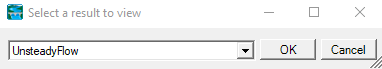
Another way to access the 3D Viewer is by right clicking on a particular result and selecting the View Result in 3D menu item.
The last way to access the 3D Viewer is by right clicking a particular result map and selecting the View Map in 3D Viewer menu item.
Pre-processing Results for 3D Viewer
Performing any of the various ways to access the 3D Viewer will bring up a pre-processing window if this is the first time you have run the 3D Viewer or if you have cancelled pre-processing the last time you opened this result in the 3D Viewer.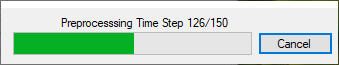
The 3D Viewer has to do much more processing compared to RAS Mapper to show a time step in the simulation. Pre-processing offloads the processing to a file in the same directory as the result file that was selected. It will be named the same except the extension will be sqlite. ![]()
Pre-processing will make subsequent loading for this result to be a smoother experience. It will also make playing the results animation smoother. Pre-processing is optional, press the Cancel button if you do not wish to pre-process at this time.
3D Viewer
The 3D Viewer interface, shown below, is comprised of a menu, a toolbar, a mini-map and the view itself.
Menu and Options
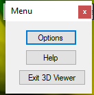
To access the menu to see options, help, and to quit the application, either click on the menu button on the top left corner or press the escape key.
When the Options button is selected a window will appear with four Tabs (General; Graphics; Controls; and Particle Tracing). The following tables describe each of the options on the four Tabs.
General Options
Table 8 1. General Options
Option | Description |
|---|---|
Water During Animation | When this option is turned on, the water resolution will be the same resolution as the terrain, based on Level of Detail settings. Animation may play slower than usual with this option turned on |
Z Scale | How much the terrain elevation is scaled by. Higher value exaggerates the elevations of the terrain, making it easier to see subtle changes in terrain. (Not Implemented Yet) |
Controls
There are three ways to control the 3D Viewer, mouse and keyboard, just mouse, and a game controller. These controls options controls certain aspects of using the mouse, keyboard, and game controller.
Table 8 2. Controls for mouse and controller sensitivity.
Option | Description |
|---|---|
Mouse Sensitivity | Controls how much the view changes with mouse movement. Higher sensitivity means more view change with mouse movement. Default is 0.1 |
Controller X Sensitivity | Control how much the view changes with the right stick of the game controller, horizontal axis only. Default is 0.3 |
Controller Y Sensitivity | Control how much the view changes with the right stick of the game controller, vertical axis only. Default is 0.15 |
Invert Y Axis | When this is turned on, moving the vertical axis on either the mouse or game controller will change the view in the opposite direction. Default is off |
Pressing the Change Key/Controller bindings button will bring up a different window where you can change the various bindings for all the controls of the 3D Viewer.
Table 8 3. Controls for Moving around within the 3D Viewer.
Action | Default Key Binding | Default Controller Binding | Description |
|---|---|---|---|
Move Forward | W | Left Stick up | Moves the viewer forward in space |
Move Backward | S | Left Stick down | Moves the viewer backward in space |
Strafe Left | A | Left Stick Left | Moves the viewer in a left side-step fashion in space |
Strafe Right | D | Left Stick Right | Moves the viewer in a right side-step fashion in space |
Increase Elevation | Space | Right Shoulder Button | Moves the viewer up in space |
Decrease Elevation | Left Control | Right Trigger Button | Moves the viewer down in space |
Change Results Map | M | Changes the results map between 4 different maps, a realistic map, depth map, velocity map, and water surface elevation map | |
Toggle Particles | P | Turns on or off the particle tracing effect | |
Flight Path Play/Pause | Return (Enter) | While a flight path is active, will either play the path or pause it. | |
Go Forward On Flight Path | Up Arrow | Up Directional Arrow | While a flight path is active, will make the viewer go forward on the flight path |
Go Backward On Flight Path | Down Arrow | Down Directional Arrow | While a flight path is active, will make the viewer go backward on the flight path |
Increase Viewer Speed | Right Arrow | Left Directional Arrow | Makes the viewer travel faster. The viewer can only go so fast however. |
Decrease Viewer Speed | Left Arrow | Right Directional Arrow | Makes the viewer travel faster. The viewer can only go so slow however. |
Turn Left | Unbound | Right Stick Left | Rotates the view to the left |
Turn Right | Unbound | Right Stick Right | Rotates the view to the right |
Change View Up | Unbound | Right Stick Up | Rotates the view up (No changeable binding yet) |
Change View Down | Unbound | Right Stick Down | Rotates the view down (No changeable binding yet) |
Toggle Mouse Pointer | Tab | A Button | Will either show or hide the mouse pointer (No changeable binding yet) |
Particle Tracing
Table 8 4. Controls for Controlling Particle Tracing.
Option | Description |
|---|---|
Speed | Refers to the animation speed of the particle trace. Default value is 1. |
Density | Refers to concentration of tracers in an area. Default value is 1. |
Width | Refers to the width of the particle. Default value is 5. |
Lifetime | Refers to how long the particle exists on screen before it disappears and a new particle spawns in its place. Default value is 300. |
| Refers to how many particles are shown at any one time. Default value is 10,000. |
RGB | Changes the color of the tracers. Each field accepts an integer between 0 and 255. R corresponds to Red, G corresponds to Green and B corresponds to Blue |
Toolbar![]()
The Toolbar is located at the top left of the 3D Viewer window. The following Table describes each of the tools.
Table 8 5. Description of each of the 3D Viewer Tools located on the Toolbar.
Tool | Description | |
|---|---|---|
Select |
| Wherever the select pointer is at, it will show the value of either the terrain elevation or water surface value, dependent on the map type chosen. |
Pan |
| Left click with the pan pointer to navigate through the terrain by clicking and dragging the terrain. |
Change Camera Modes |
| Allows you to change how the 3D Viewer is controlled. |
Zoom to Entire Extent |
| Zooms to the maximum viewable extent of the terrain, and forces the viewer to look straight down. |
Measure Tool |
| Measure the distance in map units. (Not Implemented Yet) |
Toggle Particle Tracing |
| Toggles whether particles show on the water surface. |
Particle Tracing Options |
| A shortcut to get to Particle Tracing Options |
Change Results Map |
| Changes the results map between 4 different maps, a realistic map, depth map, velocity map, and water surface elevation map |
Select a Flight Plan |
| Opens the flight plan window to choose a flight plan. See Flight Plans/Paths section for more information. |
Set to Simulation Maximum | Max | Sets the water surface to simulation maximum. (Not Implemented Yet) |
Set to Simulation Minimum | Min | Sets the water surface to simulation minimum. (Not Implemented Yet) |
Animation Bar |
| Change the animation bar position to change the time of the simulation. When a portion of the animation bar is grey, it means that the simulation has not loaded at that time yet. |
Play/Pause |
| Plays or pauses the animation |
Change Animation Speed |
| Changes the delay before changing time step in the animation. Note that there is an inherent delay that is unavoidable for each time step. That delay depends on whether you pre-processed the dataset, |
Min map
The mini map is shown to assist with acquiring bearings when using the 3D Viewer. Shown in the Figure below is an example of the mini map, which is displayed in the upper right hand corner of the 3D Viewer.
There are three components to the mini map, which are explained in the Table below.
Table 8 6. Components of the 3D Viewer Mini Map.
Component | Description |
|---|---|
Hide/Show Button | On the top right of the mini-map is a button that will hide or show the mini-map. |
Mini-map | A character on the mini-map |
Simulation Date/Time | Shows the current Date/Time for the simulation |
Speed/Position Information
On the bottom left corner of the viewer is information about the viewer's speed and its position. A description of these components is in the Table below.![]()
Table 8 7. Speed and Location Components.
Component | Description |
|---|---|
Top Speed | The maximum speed that the viewer can currently travel. Can be increased/decreased with the Increase/Decrease Viewer Speed key bindings. |
Current Speed | While the viewer is moving, the current speed will update to show the viewer's current speed. |
X,Y | The position of the viewer on the XY plane. These coordinates are the same ones used in RAS Mapper |
Z | The elevation of the viewer |
How To Use the 3D Viewer
Movement
How movement works on the keyboard/controller depends on what camera mode the 3D Viewer is currently set. By default, the 3D Viewer is set to Helicopter mode ( ![]() ), which means the movement keys will move the viewer as if it's on a geometric plane. For example, pressing the forward key will move the viewer forward.
), which means the movement keys will move the viewer as if it's on a geometric plane. For example, pressing the forward key will move the viewer forward.
Movement for the mouse works the same for either camera mode. If the cursor is currently the Select cursor ( ![]() ), middle click and drag on the terrain will move the viewer proportional to how much the mouse is dragged. If the cursor is the Pan cursor (
), middle click and drag on the terrain will move the viewer proportional to how much the mouse is dragged. If the cursor is the Pan cursor ( ![]() ), then a left click and drag is all that is needed.
), then a left click and drag is all that is needed.
Changing View/Rotation
Changing the view of the viewer is accomplished through the mouse or the right stick on the controller. It can also be done through the keyboard but the keys are unbound by default to discourage using the keyboard.
To change the view with the mouse right click and drag on the screen. This only applies when the mouse cursor is visible. If the view changes too little with the mouse drag then you can change the mouse sensitivity in the options. When the mouse cursor is not visible there is no need to right click, the view will change with mouse movement. See Mouse Lock/Unlock for more information.
To change the view with a game controller, use the right stick. This only applies when the mouse cursor is not visible. If the view changes too little with the right stick then you can change the controller sensitivity in the options. When the cursor is visible the left stick controls the mouse. See Mouse Lock/Unlock for more information.
Changing Elevation
To change the elevation with the mouse, scroll up to decrease in elevation, scroll down to increase in elevation
Changing elevation with the keyboard or game controller depends on what camera mode the 3D Viewer is currently set. By default, the 3D Viewer is set to Helicopter mode ( ![]() ), in Helicopter mode elevation is changed by pressing the Elevation Up or Elevation Down keys. In Airplane mode (
), in Helicopter mode elevation is changed by pressing the Elevation Up or Elevation Down keys. In Airplane mode ( ![]() ), these keys are disabled, and to change elevation in this mode look in the direction you wish to ascend/descend.
), these keys are disabled, and to change elevation in this mode look in the direction you wish to ascend/descend.
Mouse Lock/Unlock
By default, the mouse is shown and it considered to be "unlocked". The purpose of an unlocked mouse is to allow easy access to the buttons on the user interface.
To make changing the view with the mouse less tedious, the mouse can be "locked" to the screen by pressing the Tab key. This will hide the mouse cursor but will no longer require the mouse to right click to change view.
Flight Plans/Paths
The 3D Viewer allows the user to specify a flight path polyline in RAS Mapper for the viewer to follow like a train on tracks
Laying Out the Flight Path in RAS Mapper
To lay out a flight path, first open RAS Mapper. To open RAS Mapper, on the main RAS window select the GIS Tools | RAS Mapper menu item or by pressing the ![]() RAS Mapper button, shown below.
RAS Mapper button, shown below.
A flight path layer will be needed to lay out flight paths. To do that right click on Features Group in the tree view, and then select Create New Layer > Flightpath Layer
Then lay out the polyline you want to use for the flight plan. When you have finished right click the layer and select Stop Editing.
A shape file will be generated under the Flight Paths folder in the root project directory. Go back to the 3D Viewer and press the Select a Flight Plan button in the toolbar ( ![]() )
)
An example 3D Perspective plot is shown in Figure 6-38. The older X-Y-Z Perspective Plot of 1D cross sections is still available from the View menu.