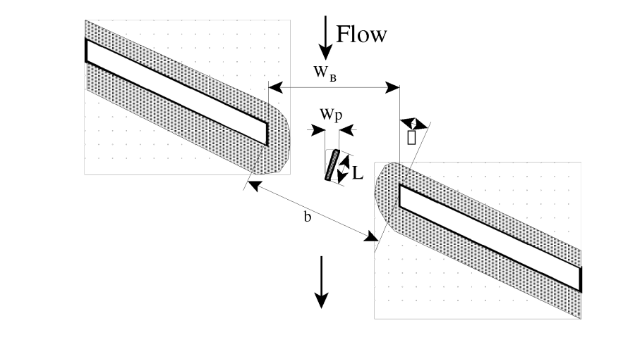
Skewed bridge crossings (the figure below) are generally handled by making adjustments to the bridge dimensions to define an equivalent cross section perpendicular to the flow lines. The bridge information, and cross sections that bound the bridge, can be adjusted from the bridge editor. An option called Skew Bridge/Culvert is available from the bridge/culvert editor.
In the publication "Hydraulics of Bridge Waterways" (Bradley, 1978) the effect of skew on low flow is discussed. In model testing, skewed crossings with angles up to 20 degrees showed no objectionable flow patterns. For increasing angles, flow efficiency decreased. A graph illustrating the impact of skew indicates that using the projected length is adequate for angles up to 30 degrees for small flow contractions.
Warning
The skew angle is based on comparing the angle of the flow as it goes through the bridge, with a line perpendicular to the cross sections bounding the bridge.
The user should not base the skew angle on the direction of the flow upstream of the bridge. When a bridge is highly skewed, most likely the flow will turn somewhat before it goes through the bridge opening. So the effective area of the opening is actually larger than if you assume an angle based on the upstream approach section.

For the example shown in the figure above, the projected width of the bridge opening, perpendicular to the flow lines, will be computed with the following equation:
| Symbol | Description | Units |
|---|
| Projected width of the bridge opening, perpendicular to the flow lines |
|
| The length of the bridge opening as measured along the skewed road crossing |
|
| The bridge skew angle in degrees. This angle is with respect to the flow going through the bridge opening and a line perpendicular to the bridge cross sections |
|
The pier information must also be adjusted to account for the skew of the bridge. HEC-RAS assumes the piers are continuous, as shown in the figure above, thus the following equation will be applied to get the projected width of the piers, perpendicular to the flow lines:
| 2) |
W_p =sin \theta *L+cos \theta *w_p |
| Symbol | Description | Units |
|---|
| The projected width of the pier, perpendicular to the flow lines |
|
| The actual length of the pier |
|
| The actual width of the pier |
|