Download PDF
Download page Cross Section Locations.
Cross Section Locations
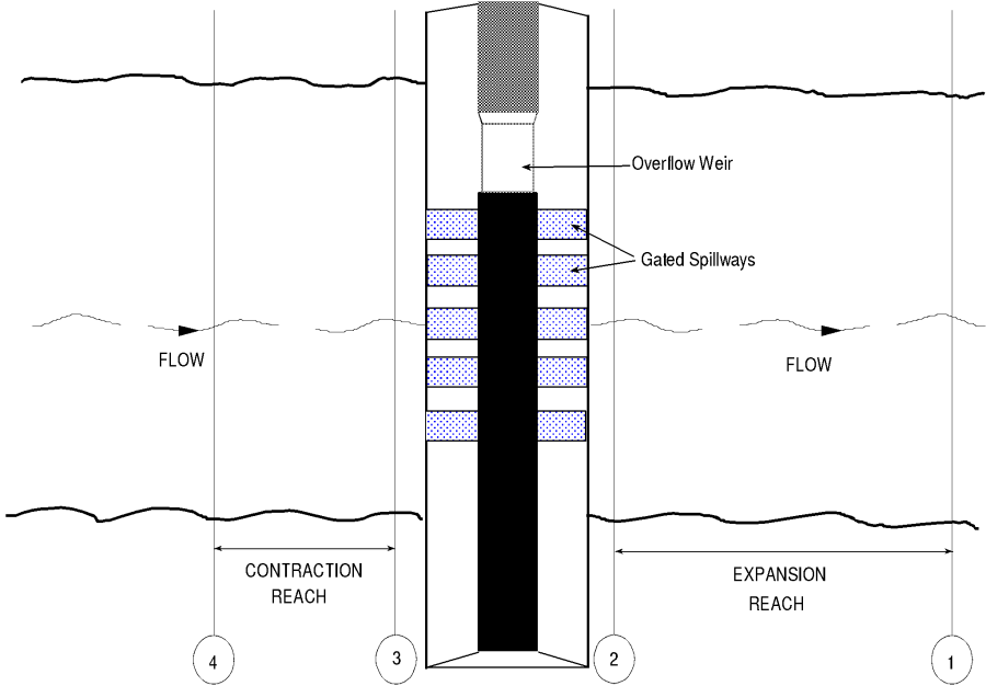
The inline weir and gated spillway routines in HEC-RAS require the same cross sections as the bridge and culvert routines. Four cross sections in the vicinity of the hydraulic structure are required for a complete model, two upstream and two downstream. In general, there should always be additional cross sections downstream from any structure (bridge, culvert, weir, etc...), such that the user entered downstream boundary condition does not affect the hydraulics of flow through the structure. In order to simplify the discussion of cross sections around the inline weir and gated spillway structure, only the four cross sections in the vicinity will be discussed. These four cross sections include: one cross section sufficiently downstream such that the flow is fully expanded; one at the downstream end of the structure (representing the tailwater location); one at the upstream end of the structure (representing the headwater location); and one cross section located far enough upstream at the point in which the flow begins to contract. Note, the cross sections that bound the structure represent the channel geometry outside of the embankment. The figure below illustrates the cross sections required for an inline weir and gated spillway model.
Cross Section 1. Cross Section 1 for a weir and/or gated spillway should be located at a point where flow has fully expanded from its constricted top width caused by the constriction. The entire area of Cross Section 1 is usually considered to be effective in conveying flow.
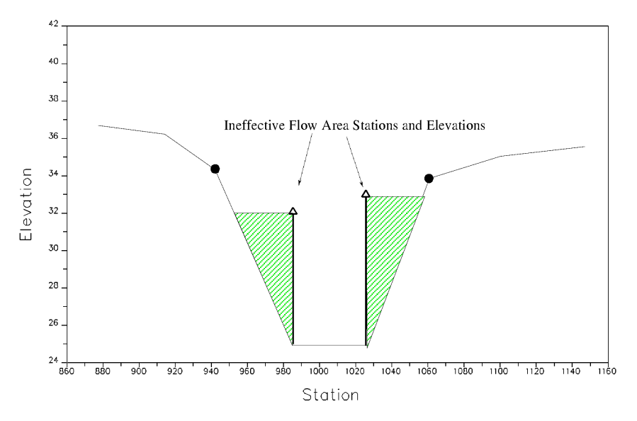
Cross Section 2. Cross Section 2 is located a short distance downstream from the structure. The computed water surface at this cross section will represent the tailwater elevation of the weir and the gated spillways. This cross section should not include any of the structure or embankment, but represents the physical shape of the channel just downstream of the structure. The shape and location of this cross section is entered separately from the Inline Weir and Gated Spillway data (from the cross section editor).
The HECRAS ineffective area option is used to restrict the effective flow area of Cross Section 2 to the flow area around or near the edges of the gated spillways, until flow overtops the overflow weir and/or embankment. The ineffective flow areas are used to represent the correct amount of active flow area just downstream of the structure. Establishing the correct amount of effective flow area is very important in computing an accurate tailwater elevation at Cross Section 2. Because the flow will begin to expand as it exits the gated spillways, the active flow area at Section 2 is generally wider than the width of the gate openings. The width of the active flow area will depend upon how far downstream Cross Section 2 is from the structure. In general, a reasonable assumption would be to assume a 1:1 expansion rate over this short distance. The figure below illustrates Cross Section 2 of a typical inline weir and gated spillway model. On the figure below, the channel bank locations are indicated by small circles and the stations and elevations of the ineffective flow areas are indicated by triangles.
Cross Sections 1 and 2 are located so as to create a channel reach downstream of the structure in which the HECRAS program can accurately compute the friction losses and expansion losses that occur as the flow fully expands.
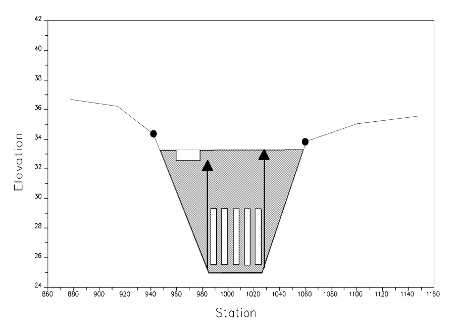
Cross Section 3. Cross Section 3 of an inline weir and gated spillway model is located a short distance upstream of the embankment, and represents the physical configuration of the upstream channel. The water surface computed at this cross section represents the upstream headwater for the overflow weir and the gated spillways. The software uses a combination of the deck/road embankment data, Cross Section 3, and the gated spillway data, to describe the hydraulic structure and the roadway embankment. The inline weir and gated spillway data are located at a river station between Cross Section 2 and Cross Section 3.
The HECRAS ineffective area option is used to restrict the effective flow area of Cross Section 3 until the flow overtops the roadway. The ineffective flow area is used to represent the correct amount of active flow area just upstream of the structure. Because the flow is contracting rapidly as it enters the gate openings, the active flow area at Section 3 is generally wider than the width of the gates. The width of the active flow area will depend upon how far upstream Cross Section 3 is placed from the structure. In general, a reasonable assumption would be to assume a 1:1 contraction rate over this short distance. The figure below illustrates Cross Section 3 for a typical model, including the embankment profile and the gated spillways. On the figure below, the channel bank locations are indicated by small circles, and the stations and elevations of ineffective areas are indicated by triangles.
Cross Section 4. The final cross section in the inline weir and gated spillway model is located at a point where flow has not yet begun to contract from its unrestrained top width upstream of the structure. This distance is normally determined assuming a one to one contraction of flow. In other words, the average rate at which flow can contract to pass through the gate openings is assumed to be one foot laterally for every one foot traveled in the downstream direction. The entire area of Cross Section 4 is usually considered to be effective in conveying flow.