Download PDF
Download page Hydraulic Computations through Gated Spillways.
Hydraulic Computations through Gated Spillways
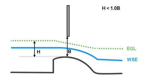
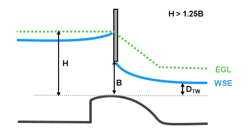
HEC-RAS is capable of modeling radial gates (often called tainter gates), vertical lift gates (sluice gates), and overflow gates. The equations used to model the gate openings can handle both submerged and unsubmerged conditions at the inlet and the outlet of the gates. When the gates are opened to an elevation greater than the Headwater energy depth (H) (defined as the difference between the Energy Grade Line and the spillway crest), the program automatically switches to modeling the flow through the gates as weir flow. When the upstream water surface is greater than or equal to 1.25 times the height of the gate opening, the orifice flow equation is applied. When the upstream water surface is between 1.0 and 1.25 times the gate opening (B), the flow is in a zone of transition between weir flow and gate flow. The program computes the upstream head with both equations and then calculates a linear weighted average of the two values (this is an iterative process to obtain the final headwater elevation for a flow in the transition range).
A summary of types of flow through gated spillways is provided below. The form of the equations discussed is simplified to assume a rectangular shape where flow area can be computed as the height of the gate opening times the gate width. The types of flow through gates is weir flow (free flow), unsubmerged orifice flow (sluice flow), submerged orifice flow, and transition flow (transitional between unsubmerged and submerged orifice flow).
Weir Flow (Free Flow)
Free flow occurs when the Energy Grade Line is below the bottom of the gate. Flow is computed using the Weir Flow equation shown below, where the Energy Grade Line is used to compute the "head" above the sill of the weir, Headwater energy depth (H). Additional considerations are evaluated for user-specified weirs such as ogee crested, broad crested, and sharp crested shapes. Submergence is also considered. The simple form of the weir equation is shown below.
| Q=C_wLH^{3/2} |

The transition to gate flow occurs when the Energy Grade Line hits the bottom of the gate at which point the gate is evaluated for sluice flow and/or orifice flow. The transition from weir flow to gate flow occurs when the Headwater energy depth (H) divided by the gate opening (B) is between 1.0 and 1.25. Flow is computed as a linear transition from weir flow to sluice flow in this range.
Unsubmerged Orifice Flow (Sluice Flow)
Unsubmerged orifice (also known as sluice or free orifice) gate flow occurs when the Headwater energy depth (H) is greater than 1.25 times the gate opening height (B) and the submergence (SB), defined as the Tailwater Depth (DTW) divided by the Headwater energy depth (H), is less than 0.67. The simple form of the sluice gate equation is shown below.
| Q=C_uWB \sqrt{2gH} |

Submerged Orifice Flow
Submerged orifice flow occurs when the Headwater energy depth (H) is greater than 1.25 times the gate opening height (B) and the submergence (SB), defined as the Tailwater Depth (DTW) divided by the Headwater energy depth (H), is greater than 0.8. The submerged orifice equation is shown below, where Ho is defined by the difference between the upstream Energy Grade Line and the downstream Water Surface Elevation.
| Q=C_sWB\sqrt{2gH_o} |

Transition Flow (Unsubmerged to Submerged Orifice Flow)
Transition flow occurs when the submergence (SB) is between 0.67 and 0.80. Flow is computed as a linear transition from sluice flow to submerged orifice flow. The head (Ho) used for computing flow through the transition zone is defined as the difference between the upstream Energy Grade Line and the downstream Water Surface Elevation.
When SB = 0.67, H_o is essentially \frac{1}{3}H and the unsubmerged form of the orifice equation is equivalent to Q=C_uWB \sqrt{2g(3H_o)}.
Therefore, total orifice flow through the transition is computed from a portion of each of the unsubmerged and submerged flow equations, as shown below.
| Q_{total} = C_uWB \sqrt{2g(3H_o)}(1-fraction) + C_sWB\sqrt{2g(H_o)}(fraction) |
where: fraction={(SB-0.67)\over(0.8-0.67)} and SB is the submergence.
Below 0.67 submergence, only the unsubmerged orifice equation is used. Above 0.8, only the submerged orifice equation is used. Between 0.67 and 0.8, both equations are computed and the final flow is computed as a linear transition between between 0.67 and 0.8.
