Download PDF
Download page FHWA Chart and Scale Numbers.
FHWA Chart and Scale Numbers
The FHWA chart and scale numbers are required input data. The FHWA chart number and scale number refer to a series of nomographs published by the Bureau of Public Roads (now called the Federal Highway Administration) in 1965 [BPR, 1965], which allowed the inlet control headwater to be computed for different types of culverts operating under a wide range of flow conditions. These nomographs and others constructed using the original methods were republished [FHWA, 1985]. The tables in this chapter are copies of the information from the 1985 FHWA publication.
Each of the FHWA charts has from two to four separate scales representing different culvert entrance designs. The appropriate FHWA chart number and scale number should be chosen according to the type of culvert and culvert entrance. Table 6-6 may be used for guidance in selecting the FHWA chart number and scale number.
Chart numbers 1, 2, and 3 apply only to pipe culverts. Similarly, chart numbers 8, 9, 10, 11, 12, and 13 apply only to box culverts. The HEC‑RAS program checks the chart number to assure that it is appropriate for the type of culvert being analyzed. HEC‑RAS also checks the value of the Scale Number to assure that it is available for the given chart number. For example, a scale number of 4 would be available for chart 11, but not for chart 12.
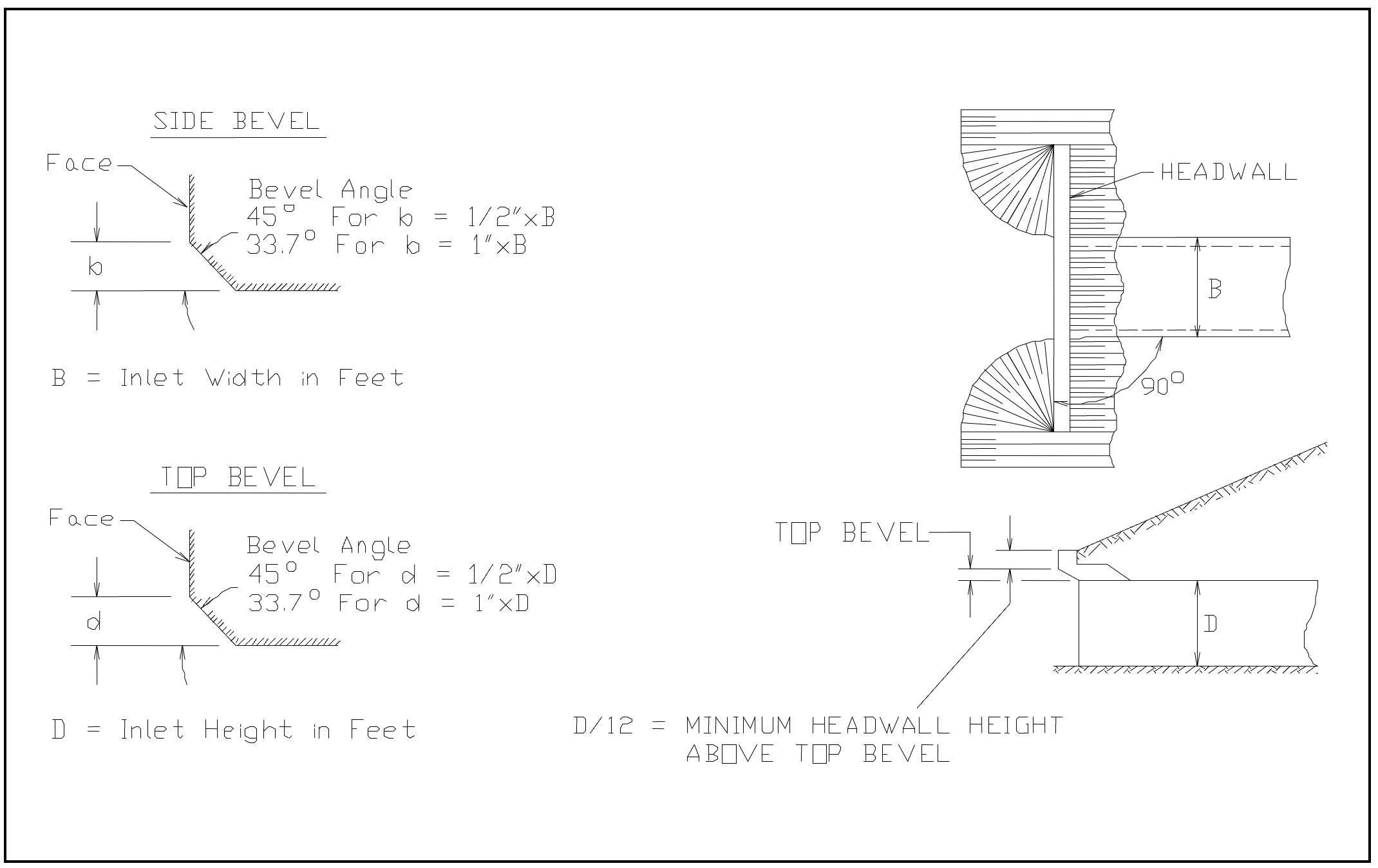
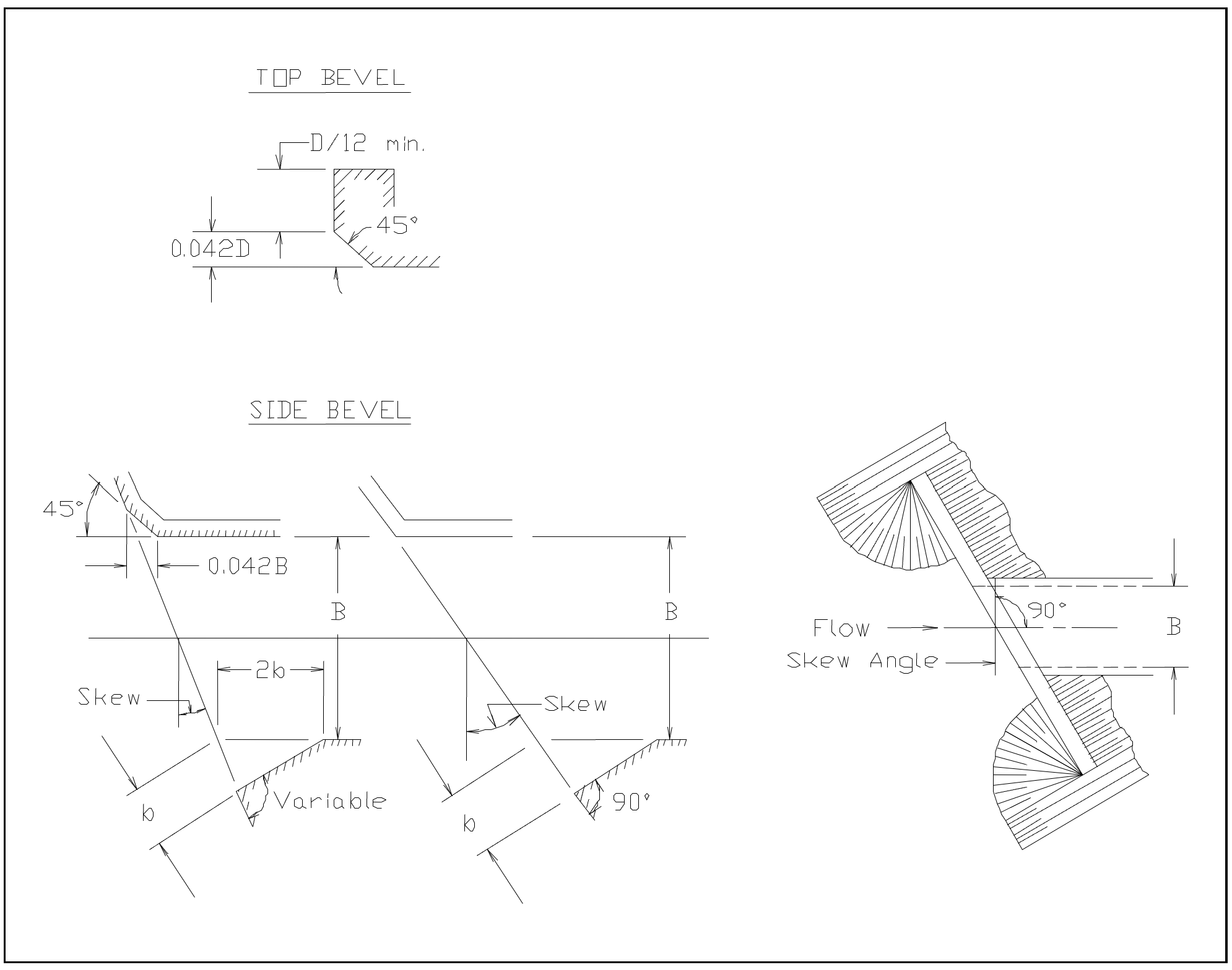
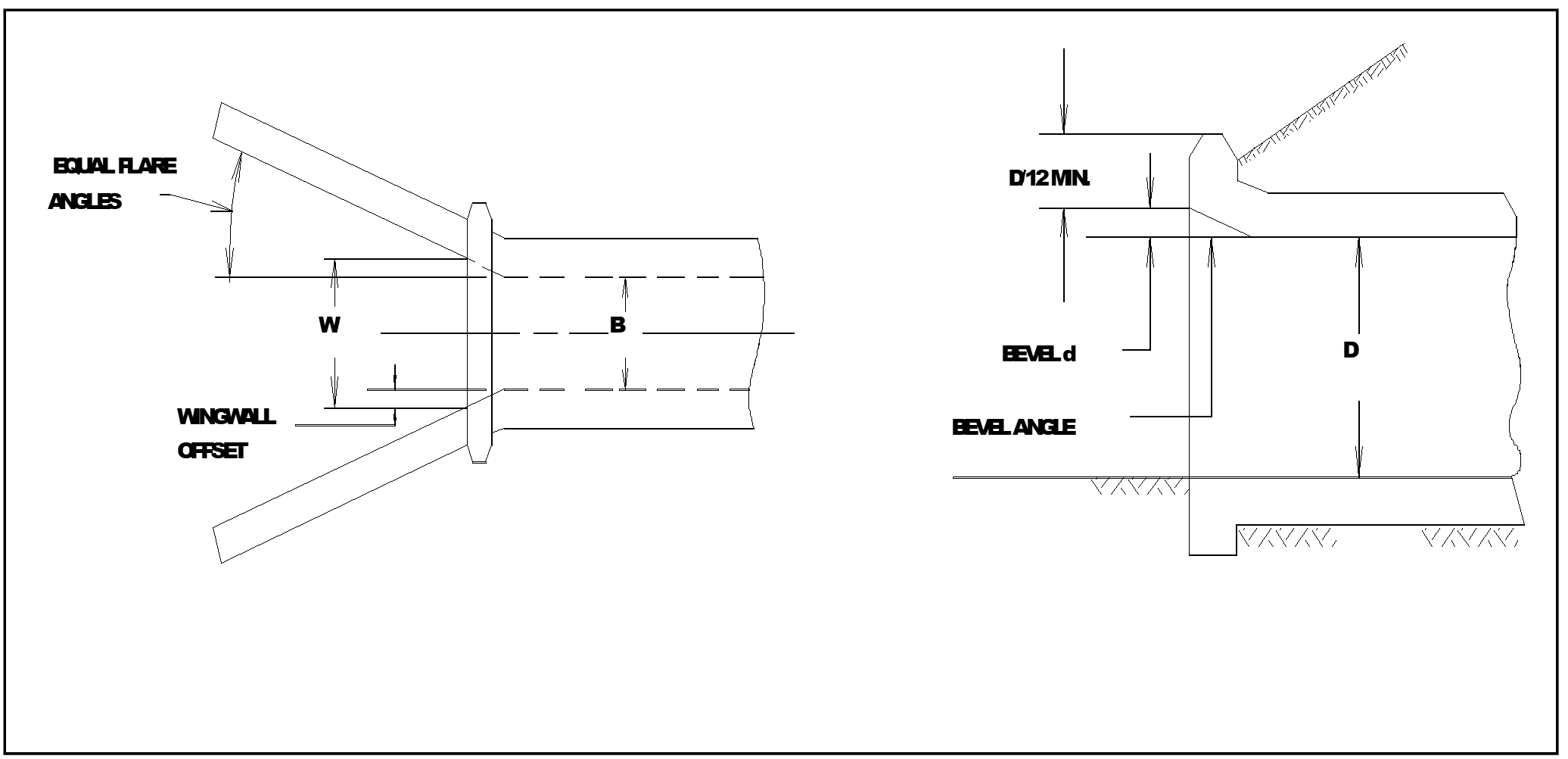
The following figures can be used as guidance in determining which chart and scale numbers to select for various types of culvert inlets.
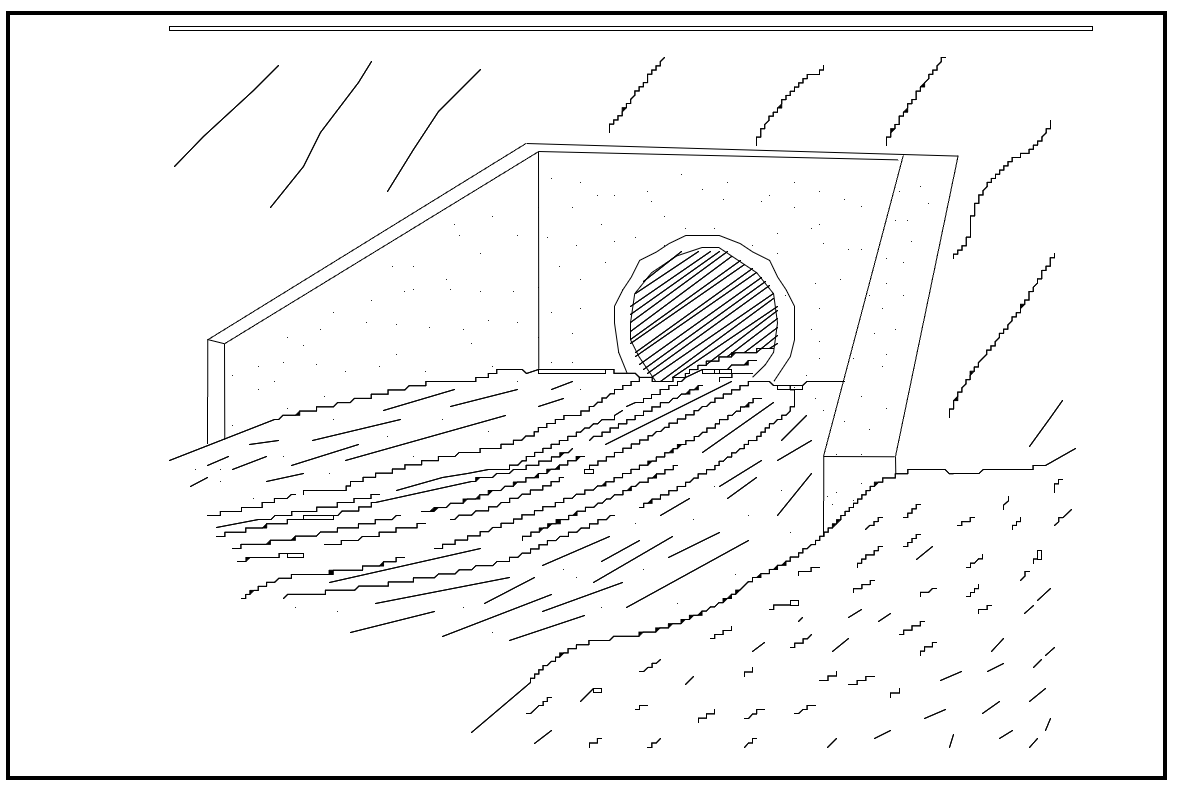
Table 6‑6 FHWA Chart and Scale Numbers for Culverts
Chart | Scale |
|
|---|---|---|
1 | Concrete Pipe Culvert | |
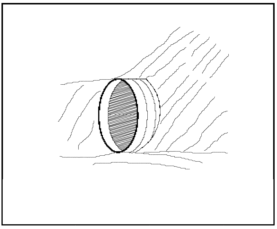
1 | Square edge entrance with headwall (See Figure 6-10) | |
2 | Corrugated Metal Pipe Culvert | |
1 | Headwall (See Figure 6-10) | |
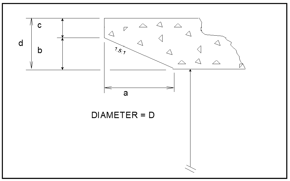
3 | Concrete Pipe Culvert; Beveled Ring Entrance (See Figure 6-13) | |
1(A) | Small bevel: b/D = 0.042; a/D = 0.063; c/D = 0.042; d/D = 0.083 | |
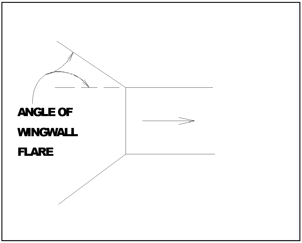
8 | Box Culvert with Flared Wingwalls (See Figure 6-14) | |
1 | Wingwalls flared 30 to 75 degrees | |
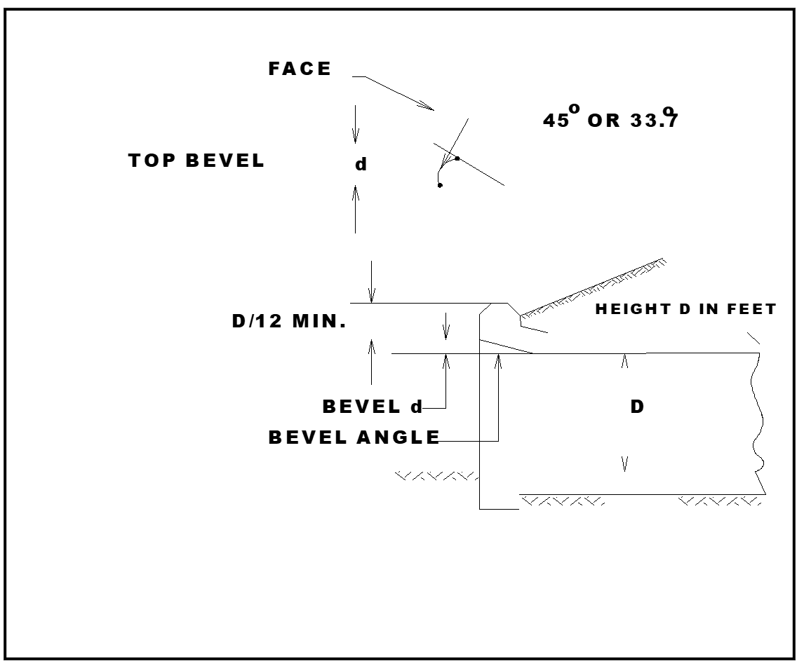
9 | Box Culvert with Flared Wingwalls and Inlet Top Edge Bevel (See Figure 6-15) | |
1 | Wingwall flared 45 degrees; inlet top edge bevel = 0.043D | |
10 | Box Culvert; 90-degree Headwall; Chamfered or Beveled Inlet Edges (See Figure 6-16) | |
1 | Inlet edges chamfered 3/4-inch | |
11 | Box Culvert; Skewed Headwall; Chamfered or Beveled Inlet Edges (See Figure 6-17) | |
1 | Headwall skewed 45 degrees; inlet edges chamfered 3/4-inch | |
12 | Box Culvert; Non-Offset Flared Wingwalls; 3/4-inch Chamfer at Top of Inlet | |
1 | Wingwalls flared 45 degrees (1:1); inlet not skewed | |
13 | Box Culvert; Offset Flared Wingwalls; Beveled Edge at Top of Inlet (See Figure 6-19) | |
1 | Wingwalls flared 45 degrees (1:1); inlet top edge bevel = 0.042D | |
16-19 | Corrugated Metal Box Culvert | |
1 | 90 degree headwall | |
29 | Horizontal Ellipse; Concrete | |
1 | Square edge with headwall | |
30 | Vertical Ellipse; Concrete | |
1 | Square edge with headwall | |
34 | Pipe Arch; 18" Corner Radius; Corrugated Metal | |
1 | 90 Degree headwall | |
35 | Pipe Arch; 18" Corner Radius; Corrugated Metal | |
1 | Projecting | |
36 | Pipe Arch; 31" Corner Radius; Corrugated Metal | |
1 | Projecting | |
41-43 | Arch; low-profile arch; high-profile arch; semi circle; Corrugated Metal | |
1 | 90 degree headwall | |
55 | Circular Culvert | |
1 | Smooth tapered inlet throat | |
56 | Elliptical Inlet Face | |
1 | Tapered inlet; Beveled edges | |
57 | Rectangular | |
1 | Tapered inlet throat | |
58 | Rectangular Concrete | |
1 | Side tapered; Less favorable edges | |
59 | Rectangular Concrete | |
1 | Slope tapered; Less favorable edges | |
60 | ConSpan Span/Rise Approximately 2:1 | |
1 | 0 degree wingwall angle | |
61 | ConSpan Span/Rise Approximately 4:1 | |
1 | 0 degree wingwall angle |
